Laminated composite, information recording medium, and member of imparting forgery-preventing characteristic

Inactive Publication Date: 2005-10-18
TOPPAN PRINTING CO LTD
View PDF30 Cites 20 Cited by
  • Summary
  • Abstract
  • Description
  • Claims
  • Application Information

AI Technical Summary

Benefits of technology

[0037]As described in the above, a latent image-forming layer having the oriented portion and the non-oriented portion is combined with an optical layer or a light reflective substrate in the present invention. The oriented portion and non-oriented portion compose the latent image. Generally, they differ only in orientation state of the main chains or side chains of molecules of the liquid crystalline polymer material or both of them. The difference in orientation state between the first portion and the second portion cannot be distinguished by direct visual observation. However, if a polarizing member is used, the difference between them can be visually observed as differenc

Problems solved by technology

The conventional forgery-preventing techniques using a

Method used


Image

  • Laminated composite, information recording medium, and member of imparting forgery-preventing characteristic
  • Laminated composite, information recording medium, and member of imparting forgery-preventing characteristic
  • Laminated composite, information recording medium, and member of imparting forgery-preventing characteristic

Examples


Example

EXAMPLE 1

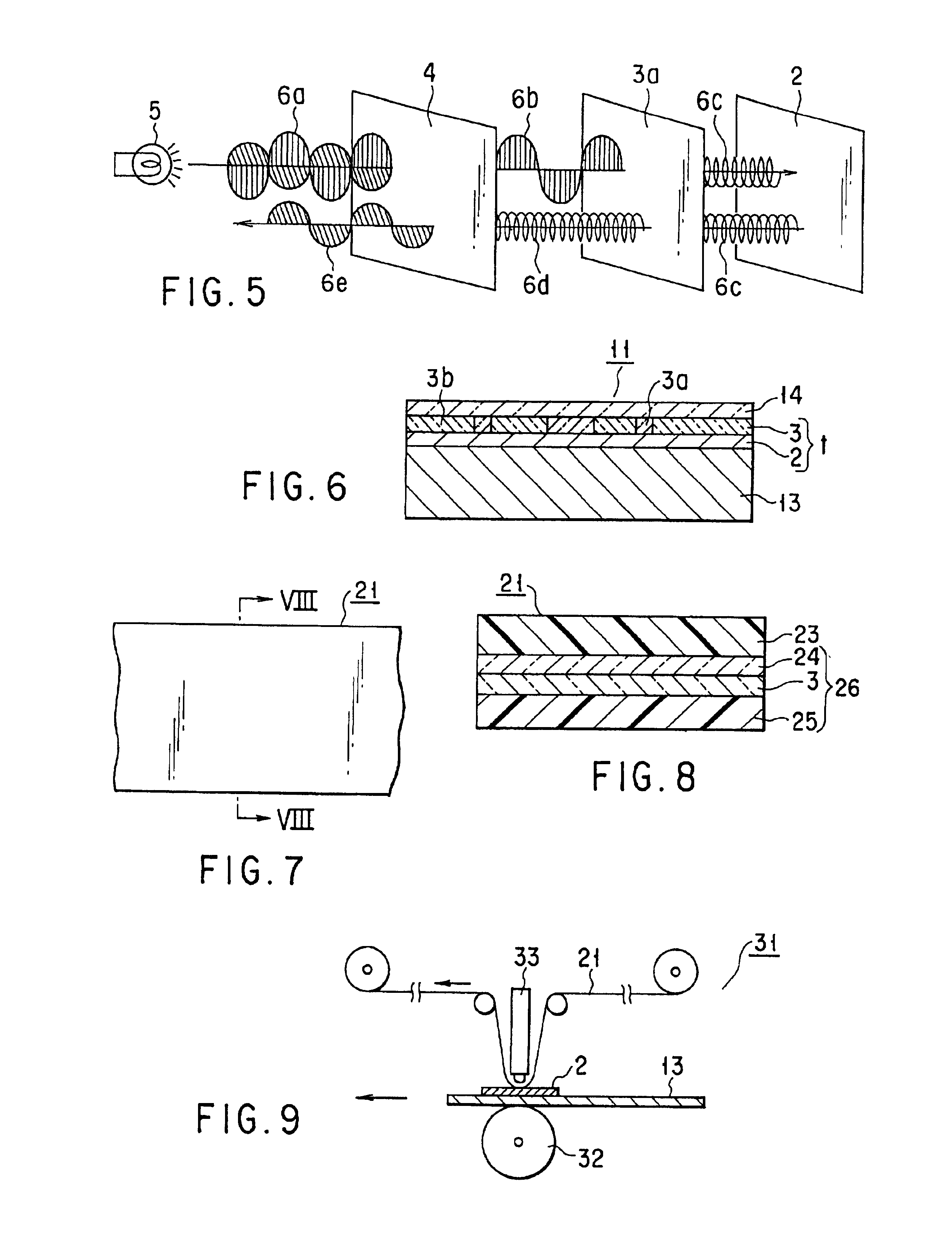
[0167]The information recording medium 11 shown in FIG. 6 was manufactured by the following method. First, a metal layer of about 60 nm thick was formed as a specular reflection layer 2 by a vacuum evaporation method on one of the main surfaces of a polyethylene terephthalrate (PET) substrate 13 of 50 μm thick. Second, on the specular reflection layer 2, a latent image formation layer 3 was formed by a gravure method using a coating liquid for a latent-image formation layer having a composition shown below. Note that the temperature for drying was 60° C. and coating thickness was 0.5 μm.

[0168]Composition of the coating liquid for a latent image formation layer

[0169]Liquid crystalline polymer:20 parts by weight[Chiracoal PLC-7003 manufactured by Asahi DenkaKogyo K.K.]MEK:80 parts by weight

[0170]Thereafter, an FDS medium TP (manufactured by Toyo Ink Manufacturing Co., Ltd.) was print-coated, as an anchor medium, on the latent image formation layer 3 with a thickness of about ...

Example

EXAMPLE 2

[0173]An information recording medium 11 was manufactured in the same manner as Example 1 except that a latent image was formed by thermal head printing in place of hot stamping. When the information recording medium 11 having a latent image thus formed was visually observed, the latent image could not be recognized and the medium 11 looked as a mere metal deposited medium. In contrast, when the information recording medium 11 was observed through a circularly polarizing film 4, the latent image was clearly observed as a visible image regardless of observation angle. In this example, since the latent image was formed by thermal head printing, any pattern of the latent image could be formed.

Example

EXAMPLE 3

[0174]The adhesive-backed sheet 21 shown in FIGS. 7 and 8 was manufactured by the following method. An information recording medium 11 shown in FIGS. 11 and 12 was manufactured by using the sheet 21.

[0175]A releasable protection layer 24 of about 1.0 μm thick was formed on one of the major surfaces of a transparent PET base 23 of 12 μm thick by a gravure method using a coating liquid for a releasable protection layer having the composition shown below.

[0176]Composition of the coating liquid for releasable protection layer

[0177]Acrylic resin:20 parts by weight[BR-80 manufactured byMitsubishi Rayon Co., Ltd.]Toluene:40 parts by weightMEK:35 parts by weightEthyl acetate: 5 parts by weight

[0178]Next, on the releasable protection layer 24, a latent image formation layer 3 was formed by a gravure method using a coating liquid for a latent image formation layer having the composition shown below. The temperature for drying was 60° C. and the coating thickness was 0.5 μm.

[0179]Comp...


PUM

PropertyMeasurementUnit
Lengthaaaaaaaaaa
Percent by massaaaaaaaaaa

Abstract

According to the present invention, there is provided a laminated composite including an optical layer having a light reflectivity, and a latent image formation layer containing a liquid crystalline polymer material and provided on one of major surfaces of the optical layer, wherein the latent image formation layer includes at least one oriented portion in an orientation state and at least one non-oriented portion in a non-orientation state, and the oriented and non-oriented portions constitute a latent image which is unrecognizable by a direct visual observation and recognizable by a visual observation through a polarizing member. Also, according to the present invention, there is provided an information recording medium and a member of imparting a forgery-preventing characteristic including such a latent image formation layer.

Description

CROSS-REFERENCE TO RELATED APPLICATIONS[0001]This is a Continuation Application of PCT Application No. PCT / JP00 / 03292, filed May 23, 2000, which was not published under PCT Article 21(2) in English.[0002]This application is based upon and claims the benefit of priority from the prior Japanese Patent Application No. 11-143998, filed May 24, 1999, the entire contents of which are incorporated herein by reference.BACKGROUND OF THE INVENTION[0003]1. Field of the Invention[0004]The present invention relates to a laminated composite, an information recording medium, and a member of imparting a forgery-preventing characteristic, and more particularly, to a laminated composite which can be used in discriminating an information recording medium between genuine one and a counterfeit by using a latent image, an information recording medium which can be discriminated between a genuine one and a counterfeit by using the latent image, a member of imparting, to an information recording medium, a f...

Claims


Application Information

Patent Timeline
IPC IPC(8): B42D15/00B41M3/14B41M5/36G02B5/30B41M5/40B41M5/41B41M5/42B44F1/12
CPCB41M3/14B41M5/36G02B5/3016B42D25/29Y10T428/1471B41M5/41B41M5/42B42D2033/26G03H1/0011G03H1/0256G03H2250/38Y10S283/904Y10T428/10Y10T428/1005Y10T428/1036Y10T428/1041Y10T428/14B41M3/148C09K2323/03C09K2323/02C09K2323/00C09K2323/031B42D25/364
Inventor GOCHO, SATOSHIKIJIMA, ATSUSHIKUBO, AKIRAITO, NORIYUKISHINDO, NAOAKI
Owner TOPPAN PRINTING CO LTD
Why Eureka
Try Eureka