Acoustical and thermal insulator

a technology of applied in the direction of roofs, instruments, pedestrian/occupant safety arrangements, etc., can solve the problems of reducing the cooling efficiency of the surrounding mechanical components, limiting the selection of construction materials, and not providing the best acoustical insulation, etc., to achieve improved acoustical and thermal insulation, strong thermal and acoustical insulation properties, and reduced melting points

Inactive Publication Date: 2005-10-18
OWENS CORNING INTELLECTUAL CAPITAL LLC
View PDF65 Cites 71 Cited by
  • Summary
  • Abstract
  • Description
  • Claims
  • Application Information

AI Technical Summary

Benefits of technology

[0007]In accordance with the purposes of the present invention as described herein, an improved acoustical and thermal insulator is provided. That insulator comprises a multi-layer composite including (a) a first facing layer such as a heat reflective material layer, (b) a polymer based blanket layer and (c) an insulation insert encapsulated by the polymer based blanket layer and the heat reflective material layer. In use on a vehicle, the insulator is mounted with the first facing or heat reflective layer closest to the heat source so that the heat is reflected away from the passenger compartment without allowing it to be adsorbed by the insulator. Accordingly, the heat reflective material layer also protects the remaining portions of the insulator i...

Problems solved by technology

This adsorption of heat limits construction material selection to relatively high melting point materials and reduces cooling efficiency of the surrounding mechanical components.
While such an insulator provides very good thermal insulation, it does not provide the best acou...

Method used


Image

  • Acoustical and thermal insulator
  • Acoustical and thermal insulator

Examples


first embodiment

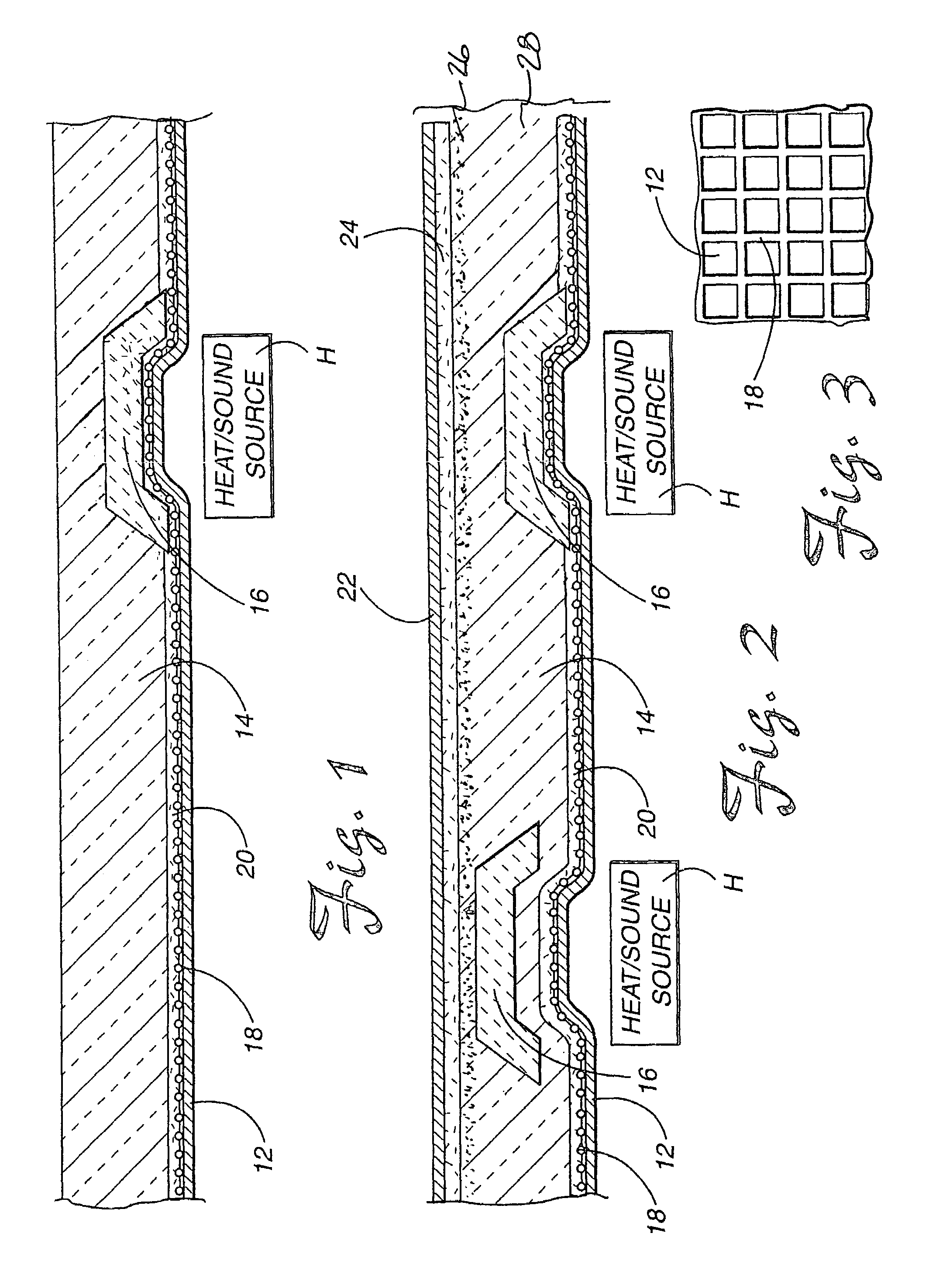
[0021]Reference is now made to FIG. 1 showing the acoustical and thermal insulator 10 of the present invention. The insulator 10 comprises a multilayer composite including a first facing layer such as a heat reflective layer 12, a polymer based blanket layer 14 and an insulation insert 16 that is encapsulated by the heat reflective layer and the polymer based blanket layer.

[0022]The first facing layer 12 may be made from polyester, polypropylene, rayon, nylon, glass and any combination thereof. In applications requiring superior heat insulative characteristics, the facing layer 12 may be formed from a heat reflective material such as a metallic foil (eg. aluminum or other heat reflective metal). Where a metallic foil is used foil thickness is generally in the range of 0.5–5.0 mil. In most applications, a foil thickness of between substantially 0.5–2.0 mil (e.g. 1.0 mil) is used. The thickness selected is based upon the temperature, durability and structural requirements of the parti...

second embodiment

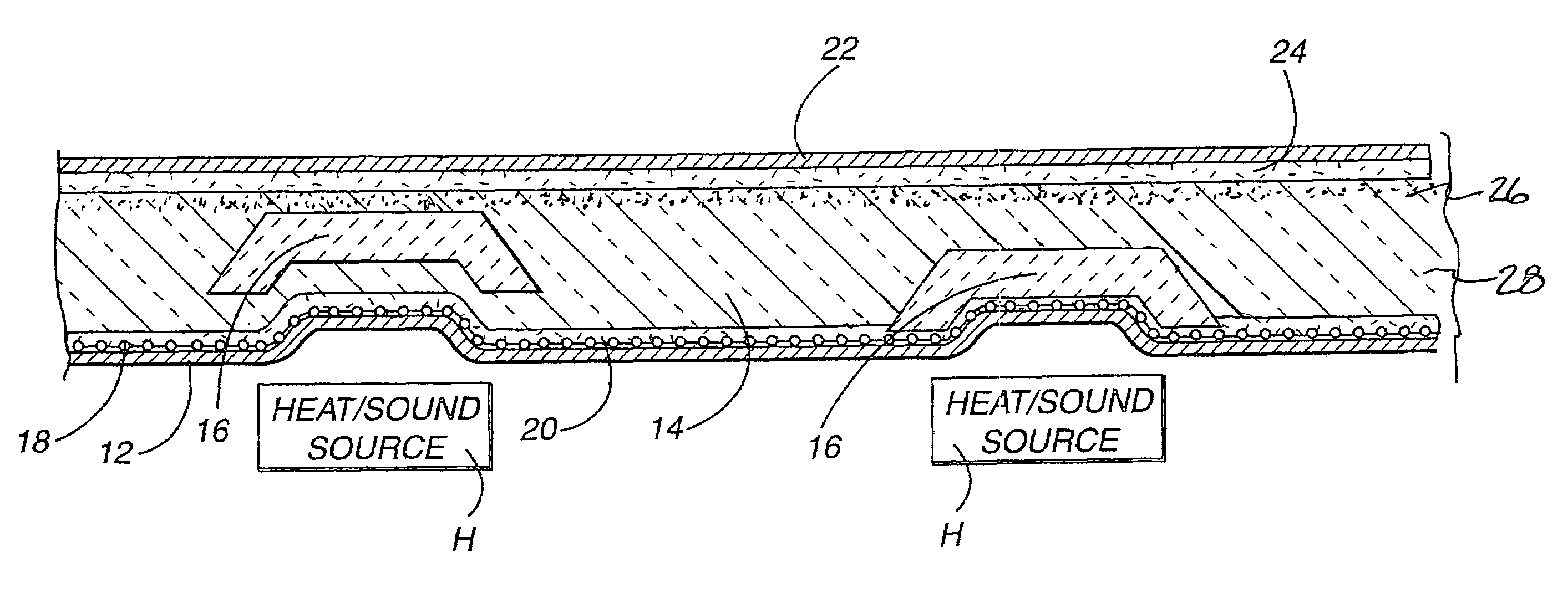
[0029]the present invention is shown in FIG. 2. Like the first embodiment shown in FIG. 1, this embodiment of the thermal insulator 10 includes a first facing layer 12, a polymer based blanket layer 14 and an insulation insert 16 of the type previously described. The first facing layer 12 is attached to the polymer based blanket layer 14 by an appropriate adhesive 20 of the type described. Additionally, this embodiment includes a second facing layer 22.

[0030]Second facing layer 22 provides a smooth durable surface for mounting the insulator 10 against a vehicle component such as a fire wall, fender well, drive shaft tunnel or passenger compartment floor pan. A number of readily available materials may be utilized to construct the second facing 22. Such materials include polyester, polypropylene, rayon, nylon, glass, metal foil and any combinations thereof (eg. polyester and rayon). Both the first and second facing layers 12, 22 may also be treated to provide enhancement of desirable...


PUM

PropertyMeasurementUnit
Thicknessaaaaaaaaaa
Densityaaaaaaaaaa
Metallic bondaaaaaaaaaa

Abstract

An acoustical and thermal insulator in the form of a multilayer composite includes a first facing layer such as a heat reflective material layer, a polymer based blanket layer and an insulation insert encapsulated in the polymer based blanket layer. The insulator may also include a second facing layer. The insulation insert is sized and positioned in the insulator so as to provide extra thermal insulation at selected hot spots and/or extra acoustical insulation at high noise points of a vehicle to which the insulator may be mounted.

Description

TECHNICAL FIELD AND INDUSTRIAL APPLICABILITY OF THE INVENTION[0001]The present invention relates generally to an acoustical and thermal insulator which may be utilized to insulate an environment such as a passenger compartment of a vehicle from the heat and sound generated by mechanical components such as the motor, drive train, suspension, tires and exhaust system of that vehicle.BACKGROUND OF THE INVENTION[0002]It is well known in the art to provide acoustical and thermal insulators on an automobile, truck or other vehicle in an effort to protect and insulate the operating or passenger compartment from the noise and heat generated by the mechanical equipment of the associated vehicle. Toward this end, mats of high temperature glass fibers have been utilized, eg. (a) on the fire wall between the dashboard and engine compartment and (b) along the floor pan of the vehicle between the passenger compartment and the drive line and exhaust system. These materials provide heat insulation ...

Claims


Application Information

Patent Timeline
IPC IPC(8): B32B15/14B32B3/02B60R13/08G10K11/00G10K11/168B32B15/08F16L59/04G10K11/16
CPCB32B3/02B32B15/14B60R13/083G10K11/168Y10T428/233Y10T428/239Y10T428/1369Y10T428/237Y10T428/1362Y10T428/1372Y10T428/1355
Inventor POOLE, PAUL WARRENBLOCK, THOMAS TROYTILTON, JEFFREY ALLAN
Owner OWENS CORNING INTELLECTUAL CAPITAL LLC
Why Eureka
Try Eureka