Method of manufacturing sputter targets with internal cooling channels
a technology of internal cooling channel and sputter target, which is applied in the direction of manufacturing tools, forging/pressing/hammering apparatus, transportation and packaging, etc., can solve the problems of high sputtering rate, bowing or bending, and causing leakage, so as to reduce bowing or bending, the effect of reducing the thermal energy of the sputter target assembly and reducing the electrical conductivity
- Summary
- Abstract
- Description
- Claims
- Application Information
AI Technical Summary
Benefits of technology
Problems solved by technology
Method used
Image
Examples
second embodiment
[0043]Turning now to FIG. 8, there is shown a sputter target assembly 205, in accordance with the present invention, subsequent to the target material 210 and backing plate material 215 being consolidated. The low temperature pressure consolidation method as discussed above with regard to the preferred embodiment is preferred. As a result of the low temperature pressure consolidation the protruding portions 240 penetrate into the target material 210 and disrupt the oxide film that may exist along the mating surface 235, thereby, promoting a metal to metal cold diffusion type bond. The tips 285, 290 deform and fold back toward the mating surfaces 225, 235, providing a physical locking mechanism, or “ZIP bond,” between the target material 210 and backing plate material 215.
[0044]With further reference to FIG. 8, the deformed edges 286, 291 of the “M” shaped protruding portions 240 are bent toward the mating surfaces 225, 235 as a result of the low temperature pressure consolidation. E...
third embodiment
[0050]The assembly 405 is then subjected to low temperature pressure consolidation as with the preceding embodiments. In this third embodiment, the protruding portions 440 are received within receptacles 496 through openings 498. The sides 485, 490 of the protruding portions 440 cooperate with the sidewalls 497, 499 of the receptacles 496, respectively, to result in a friction fit bond between the target material 410 and the backing plate material 415.
[0051]With further reference to FIG. 10, it can be seen that a portion of the mating surface 425 cooperates with the sidewalls 445, 450 and bottom portion 455 of the grooves 430 to form the cooling channels 420. The opening 460 is thereby sealed.
[0052]The low temperature annealing step, as described above in regard to the preferred embodiment, will induce improved bonding. As with the preferred embodiment, it is preferable to employ a protruding portion thickness greater than the groove width, thereby, providing for an interference fri...
sixth embodiment
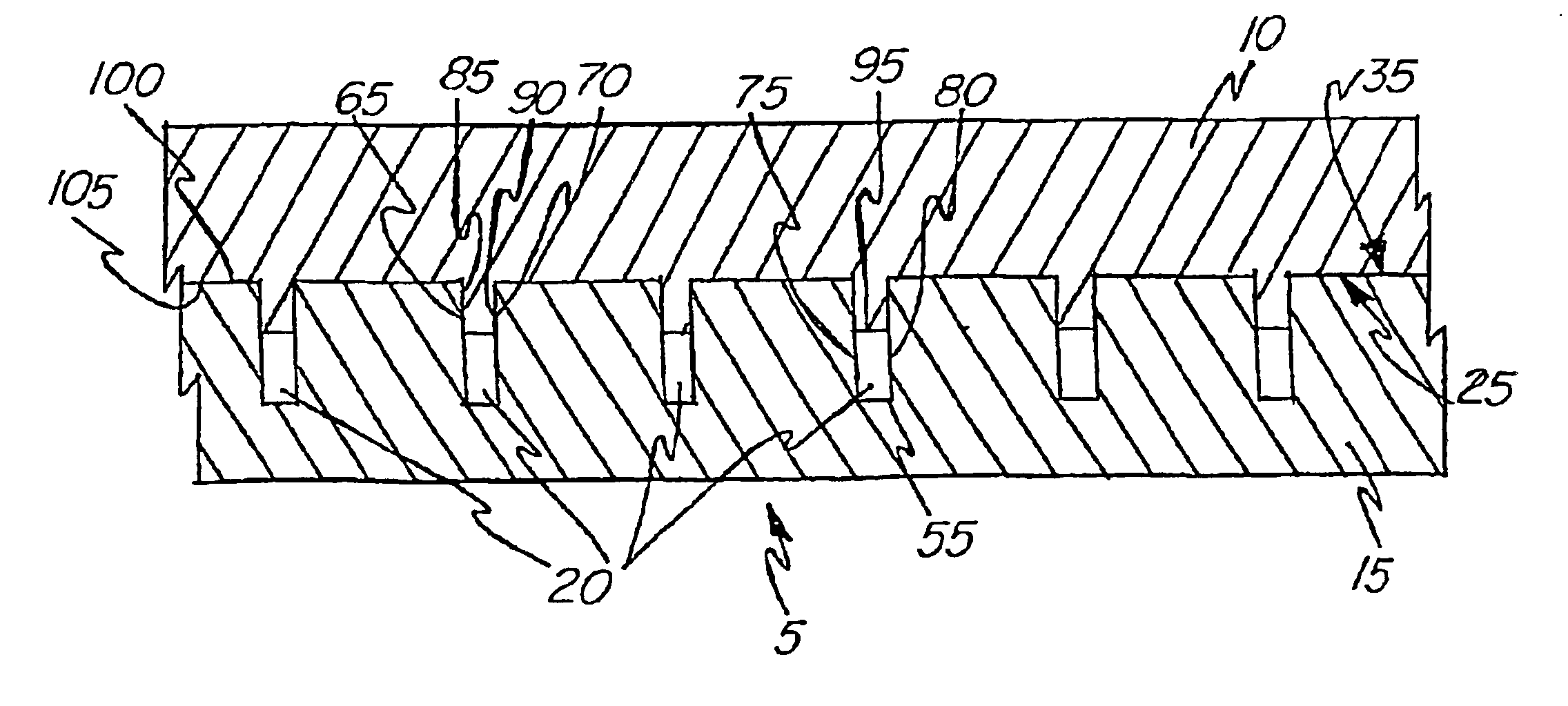
[0073]In this sixth embodiment, the lower portions 1075, 1080 and bottom portion 1055 of the grooves 1030 cooperate with the end portion 1095 of the protruding portions 1040 to define the cooling channels 1020. As can be seen in FIG. 16, the distance from the mating surface 1025 to the bottom portion 1055 of the grooves 1030, the “groove depth,” is greater than the distance from the mating surface 1035 to the end portion 1095 of the protruding portions 1040, the “protruding portion length.” The cross section of the cooling channels 1020 can be increase, or decreased, by varying the groove width or by varying the differential in the groove depth with respect to the protruding portion length.
PUM
| Property | Measurement | Unit |
|---|---|---|
| room temperature | aaaaa | aaaaa |
| temperature | aaaaa | aaaaa |
| angle | aaaaa | aaaaa |
Abstract
Description
Claims
Application Information
 - R&D
- Intellectual Property
- Life Sciences
- Materials
- Tech Scout
- Unparalleled Data Quality
- Higher Quality Content
- 60% Fewer Hallucinations
Browse by: Latest US Patents, China's latest patents, Technical Efficacy Thesaurus, Application Domain, Technology Topic, Popular Technical Reports.
© 2025 PatSnap. All rights reserved.Legal|Privacy policy|Modern Slavery Act Transparency Statement|Sitemap|About US| Contact US: help@patsnap.com


