
Node capable of saving a third layer packet handling operation in a synchronous optical network

a synchronous optical network and packet handling technology, applied in data switching networks, time-division multiplexing selection, instruments, etc., can solve the problems of large number of sdh paths (private lines), large number of sdh paths, and the limitation of the approach

Inactive Publication Date: 2005-10-18
NEC CORP
View PDF9 Cites 9 Cited by
  • Summary
  • Abstract
  • Description
  • Claims
  • Application Information

AI Technical Summary

Benefits of technology

This patent describes a system and method for efficiently transmitting data packets in a network. The system includes a node with three layers that can route and cut through packets based on their destination. By monitoring and analyzing the traffic in the network, the system can save time and resources by avoiding unnecessary operations. The method involves extracting time slots from the network, judging whether a packet is to be dropped or hopped, and transmitting the packet either through the second layer or to the next layer. The system and method can be used in a network to improve data transmission efficiency and reliability.

Problems solved by technology

However, this approach has a limit.
There remains a problem how to realize the above-mentioned demands in an IP packet network in association with an existing transmission network.
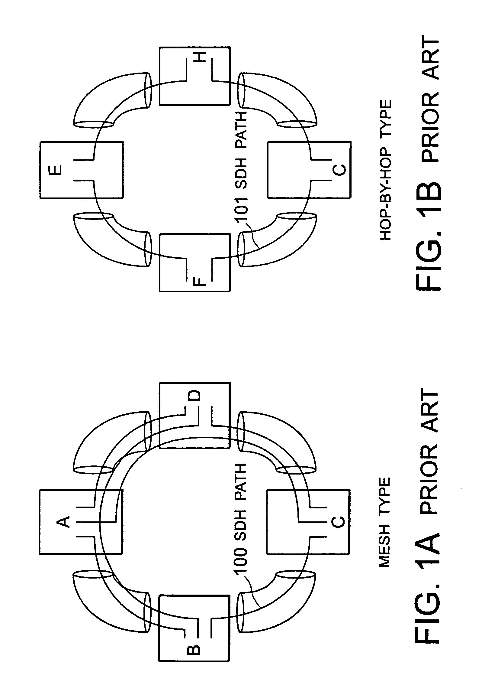
This network structure called a mesh type is disadvantageous in that a large number of SDH paths (private lines) are required.
This results in significant degradation of a network performance as a whole.
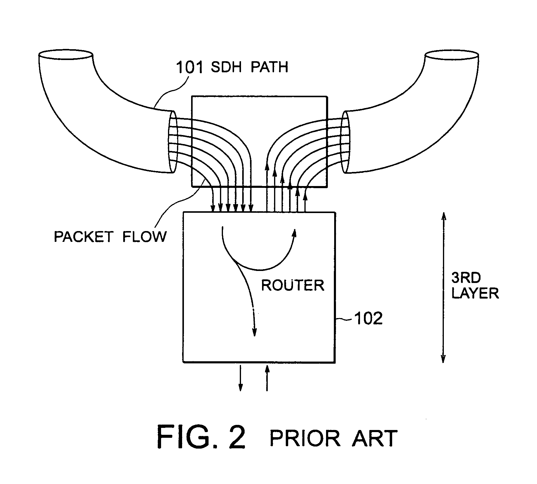
Thus, packet transfer in the above-mentioned IP packet network is disadvantageous in that the third-layer operation, i.e., the routing operation inevitably gives the heavy load.
However, since the various kinds of information must be referred to as mentioned above, packet transmission inevitably requires a complicated operation.

Method used


Image

  • Node capable of saving a third layer packet handling operation in a synchronous optical network
  • Node capable of saving a third layer packet handling operation in a synchronous optical network
  • Node capable of saving a third layer packet handling operation in a synchronous optical network

Examples


first embodiment

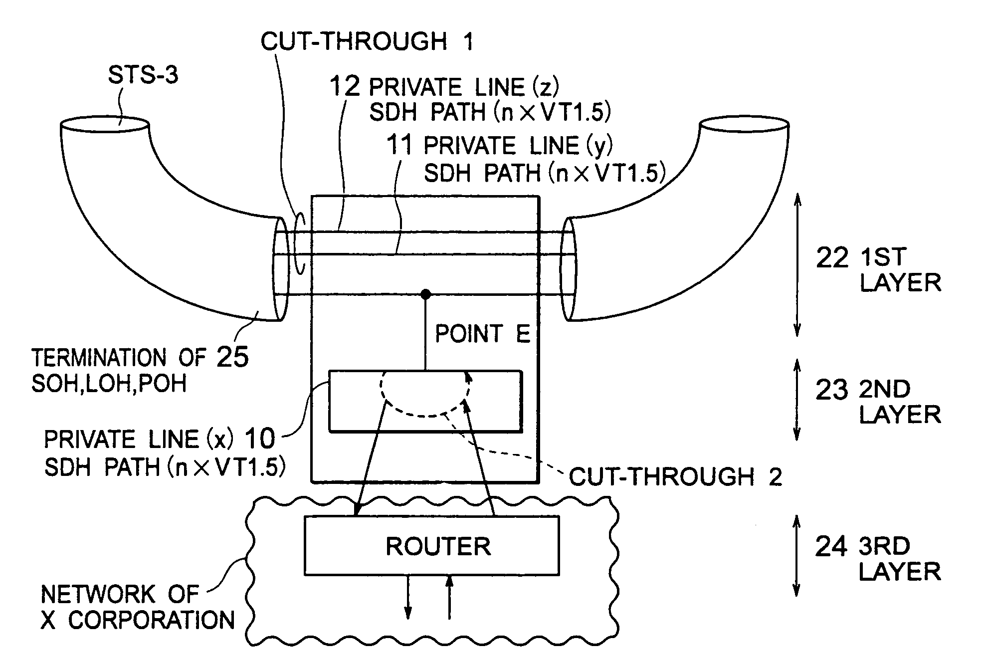
[0088]Referring to FIG. 4, description will be made about a cut-through node using a cut-through transmission apparatus according to this invention.

[0089]The cut-through node of the first embodiment is called a “cut-through 1” node.

[0090]In this embodiment, each of a plurality of SDH paths 20 is taken as a single unit for which a closed user group (CUG) is preliminarily formed.

[0091]In FIG. 4, an upper one of the SDH paths 20 does not carry any packet to be dropped at the cut-through node. In this event, the SDH path 20 is not terminated and packets on the SDH path 20 are made to pass through to a next node (cut-through 1).

[0092]In this method, not only the termination of the SDH path (for example, VT1.5) but also the operation in a second layer 23 or a third layer 24 (FIG. 5) become unnecessary. Therefore, it is possible to save a considerable amount of functions.

[0093]Furthermore, a packet delay at this node includes no more than a delay required for the packets on the SDH path 20...

second embodiment

[0098]Turning back to FIG. 4, description will be made about a cut-through node using a cut-through transmission apparatus according to this invention.

[0099]The cut-through node of this embodiment is called a “cut-through 2” node.

[0100]In the cut-through 2, if a particular SDH path 20 contains packets to be dropped and not to be dropped at this node, all packets contained in the SDH path 20 are monitored in the second layer 23. The packets not to be dropped are cut through in the second layer 23 to the next node.

[0101]In the cut-through 2 also, the SDH path 20 is not terminated and cut through to the next node in the manner similar to the cut-through 1, as depicted by a dotted line in FIG. 4.

[0102]In this embodiment, the cut-through is possible without requiring the function of terminating the SDH path (for example, VT1.5). In addition, the operation in the third layer 24 (FIG. 5) is not necessary at all. Thus, a considerable amount of functions can be saved.

[0103]A packet delay at ...


PUM


Abstract

In a node having first, second, and third layers, a packet (or a cell) is mapped in the first layer. The first layer judges whether the packet (or the cell) is to be dropped at the node or to be hopped to a next node. The first layer transmits the packet to the third layer through the second layer when the first layer judges that the packet is to be dropped at the node. The first layer transmits, when the first layer judges that the packet is to be hopped to the next node, the packet to the next node by making the packet cut through the first layer.

Description

BACKGROUND OF THE INVENTION[0001]This invention relates to a cut-through transmission apparatus and a cut-through transmission method for use in a node included in a communication network.[0002]In recent years, the internet traffic is rapidly increased. The internet traffic is carried by IP (Internet Protocol) packets which are transferred under control of a router. Following the rapid increase in internet traffic, there is a growing demand for improvement in function and performance of the router. Since most of transferred data are important data for business use, a strict demand is imposed upon the reliability, the quality, and the security. On the other hand, there arises an increasing demand for a virtual private network, such as an internet VPN service, connecting a plurality of sites or nodes.[0003]In order to meet the above-mentioned demands, one approach is to make the router have a high performance and a full of additional functions. However, this approach has a limit. Ther...

Claims


Application Information

Patent Timeline
Patent Type & Authority Patents(United States)
IPC IPC(8): G06F15/173G06F15/16H04L12/56H04J3/16H04J3/08H04J3/00H04L12/28H04L12/42H04L12/46H04L12/43H04L45/17H04Q11/04
CPCH04J3/085H04L12/2852H04L12/43H04L47/10H04L47/32H04J2203/0042H04J2203/0051H04J2203/0053H04J2203/0082
Inventor SHIMADA, NAOHIRO
Owner NEC CORP
Learn More