Scanning microscope with a detector and light source for exciting an energy state in a specimen and module for a scanning microscope

a scanning microscope and detector technology, applied in the direction of instruments, electric discharge lamps, nanotechnology, etc., can solve the problems of difficult alignment, difficult beam scanning system, and large bulky scanning microscopes for sted microscopy implemented on optical benches, etc., to achieve high spatial resolution and easy implementation

Inactive Publication Date: 2005-10-25
LEICA MICROSYSTEMS CMS GMBH
View PDF12 Cites 33 Cited by
  • Summary
  • Abstract
  • Description
  • Claims
  • Application Information

AI Technical Summary

Benefits of technology

[0012]It is therefore the object of the invention to disclose a scanning microscope for optical measurement with high spatial resolution of a ...

Problems solved by technology

Microscopes for STED microscopy are very complex and difficult to align, since the focus of the exciting light beam must always have a fixed spatial relationship to the focus of a stimulating light beam.
This problem becomes very particularly difficult in beam-scanning systems, since in these systems the foci of the exciting light beam and the detected light beam must be guided over or through the specimen simultaneously and in stat...

Method used


Image

  • Scanning microscope with a detector and light source for exciting an energy state in a specimen and module for a scanning microscope
  • Scanning microscope with a detector and light source for exciting an energy state in a specimen and module for a scanning microscope
  • Scanning microscope with a detector and light source for exciting an energy state in a specimen and module for a scanning microscope

Examples


Embodiment Construction

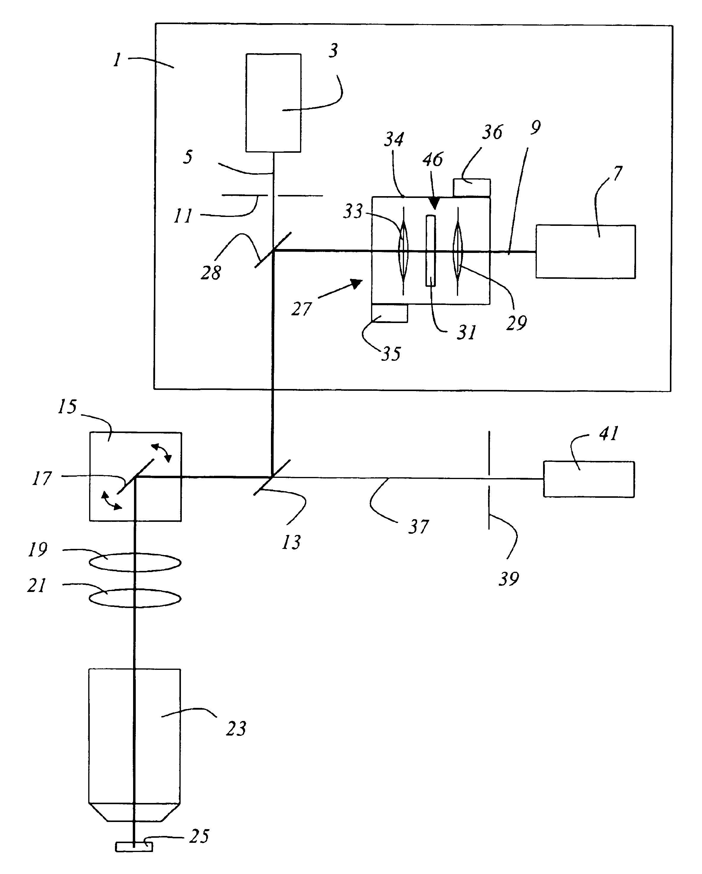
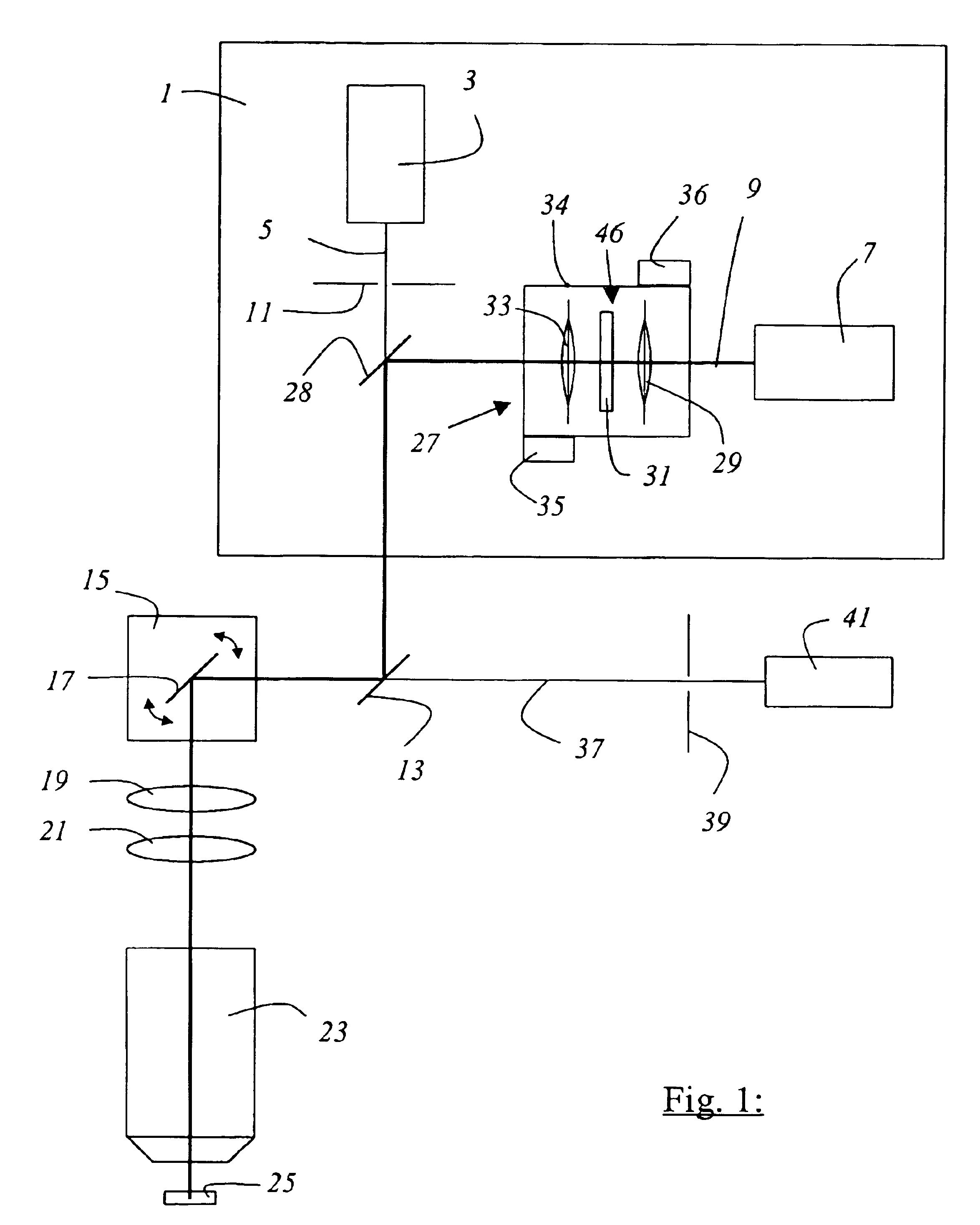
[0033]FIG. 1 shows a scanning microscope according to the present invention that is embodied as a confocal scanning microscope.

[0034]The scanning microscope contains a light source 1 that comprises a first laser 3 for generating an exciting light beam 5 and a second laser 7 for generating a stimulating light beam 9. First laser 3 is embodied as a mode-coupled titanium:sapphire laser that emits pulses having a repetition rate of approx. 80 MHz. Second laser 7 is an optically parametric oscillator which is pumped by another titanium:sapphire laser that operates in pulsed fashion and is synchronized in terms of pulse train with the first laser. Exciting light beam 5 is focused onto an illumination pinhole 11 and is then reflected by a first beam splitter 13, which is embodied as a 50:50 neutral splitter, to scan module 15, which contains a gimbal-mounted scanning mirror 17 that guides exciting light beam 5, via scanning optical system 19 and optical system 21 and through microscope opt...


PUM


Abstract

The invention discloses a scanning microscope for optical measurement with high spatial resolution of a specimen point of a specimen, having a light source for emitting an exciting light beam suitable for exciting an energy state of the specimen; a detector for detection of the emitted light; and a stimulating light beam, coming from the light source, for generating stimulated emission of the specimen excited by the exciting light beam at the specimen point, the exciting light beam and the stimulating light beam being arranged in such a way that their intensity distributions in the focal region partially overlap, wherein optical elements which shape the stimulating light beam are combined into at least one module that is positionable in the beam path of the scanning microscope.

Description

CROSS REFERENCE TO RELATED APPLICATIONS[0001]This invention claims priority of the German patent application 101 05 391.6-42 which is incorporated by reference herein.FIELD OF THE INVENTION[0002]The invention concerns a scanning microscope and a module for a scanning microscope. The invention concerns in particular a scanning microscope and a module for a scanning microscope for optical measurement with high spatial resolution of a point of a specimen.BACKGROUND OF THE INVENTION[0003]In scanning microscopy, a specimen is illuminated with a light beam in order to observe the reflected or fluorescent light emitted from the specimen. The focus of the illuminating light beam is moved by means of a controllable beam deflection device (generally by tilting two mirrors) in one specimen plane; the deflection axes are usually perpendicular to one another, so that one mirror deflects in the X and the other in the Y direction. Tilting of the mirrors is brought about, for example, with galvanom...

Claims


Application Information

Patent Timeline
IPC IPC(8): G02B21/00G02B21/06G02B21/16
CPCB82Y15/00G02B21/0032G02B21/0072G02B21/16
Inventor HOFFMANN, JUERGEN
Owner LEICA MICROSYSTEMS CMS GMBH
Why Eureka
Try Eureka