Raman amplifier, raman amplifier control method, and optical communication system

a technology of raman amplifier and control method, which is applied in the direction of fibre transmission, electrical equipment, laser details, etc., can solve the problems of difficult for conventional optical communication systems to improve the transmission capability of optical communication systems, and the power spectrum of raman-amplified signal light, which is raman-amplified multiplexed signal light, has not been sufficiently flattened, etc., to achieve high light-receiving accuracy, improve power spectrum, and improv

Inactive Publication Date: 2005-10-25
SUMITOMO ELECTRIC IND LTD
View PDF7 Cites 51 Cited by
  • Summary
  • Abstract
  • Description
  • Claims
  • Application Information

AI Technical Summary

Benefits of technology

[0020]Preferably, in the Raman amplifier according to the present invention, the pumping channels in the pumping light have a center optical frequency interval of 4 THz or less therebetween. In this case, Raman amplification bands caused by N pumping channels of pumping light having respective center optical frequencies different from each other are superposed close to each other in the optical frequency direction, whereby the power spectrum flatness of Raman-amplified signal light can be improved.
[0021]The feedback section comprises a photodetector for receiving a part of Raman-amplified signal light and outputting an electric signal corresponding to a power of the Raman-amplified signal light, and a controller for controlling the pumping light supply section according to an electric signal outputted from the photodetector. Here, the photodetector preferably includes an optical performance monitor. As a consequence, the photodetector exhibits a higher light-receiving accuracy for Raman-amplified signal, thereby being able to control the power spectrum flatness of Raman-amplified signal light at a high accuracy and improve the same.
[0022]The photodetector may comprise a demultiplexing section for demultiplexing the Raman-amplified signal light into N optical frequency ranges, and a light-receiving section for receiving each of thus demultiplexed Raman-amplified signal light components. Here, the demultiplexing section preferably includes at least one of an optical circuit comprising a dielectric optical filter, and an optical circuit comprising an optical circulator and a Bragg diffraction grating. When the light-receiving section is constituted by an optical filter made of a dielectric, the demultiplexing of Raman-amplified signal light into N optical frequency ranges different from each other can be realized at a low cost. When the optical circuit of the light-receiving section is constituted by an optical circulator and a Bragg diffraction grating, not only the demultiplexing of Raman-amplified signal light into N optical frequency ranges different from each other can be realized at a low cost, but also the light-receiving accuracy can be enhanced.

Problems solved by technology

In the case where the signal light is multiplexed in the wavelength direction (optical frequency direction), however, the power spectrum of Raman-amplified signal light, which is Raman-amplified multiplexed signal light, has not sufficiently been flattened due to the interference between signal channels having center wavelengths (center optical frequencies) different from each other.
Therefore, it has been difficult for the conventional optical communication systems to improve the transmission capability of optical communication systems.

Method used


Image

  • Raman amplifier, raman amplifier control method, and optical communication system
  • Raman amplifier, raman amplifier control method, and optical communication system
  • Raman amplifier, raman amplifier control method, and optical communication system

Examples


first embodiment

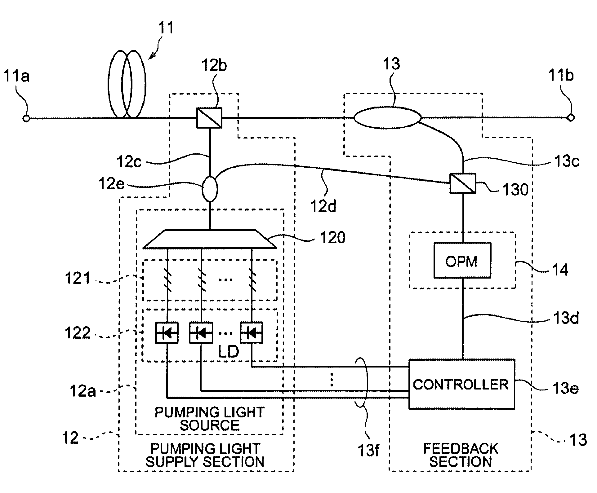
[0057]The Raman amplifier and method of controlling a Raman amplifier according to the present invention will now be explained. FIG. 7 is a diagram showing the configuration of the Raman amplifier according to the present invention. In FIG. 7, the Raman amplifier 10 comprises an optical fiber 11 for Raman-amplifying signal light propagating therethrough, a pumping light supply section 12 for supplying the optical fiber 11 with pumping light, and a feedback section 13 for detecting the signal light Raman-amplified (Raman-amplified signal light) and controlling the pumping light supply section 12 so as to flatten the power spectrum of Raman-amplified signal light according to the result of detection. Here, the signal light is one including a plurality of signal channels having respective center optical frequencies different from each other, e.g., signal light in which 40 signal channels having a center optical frequency interval of 100 GHz in terms of optical frequency are multiplexed...

second embodiment

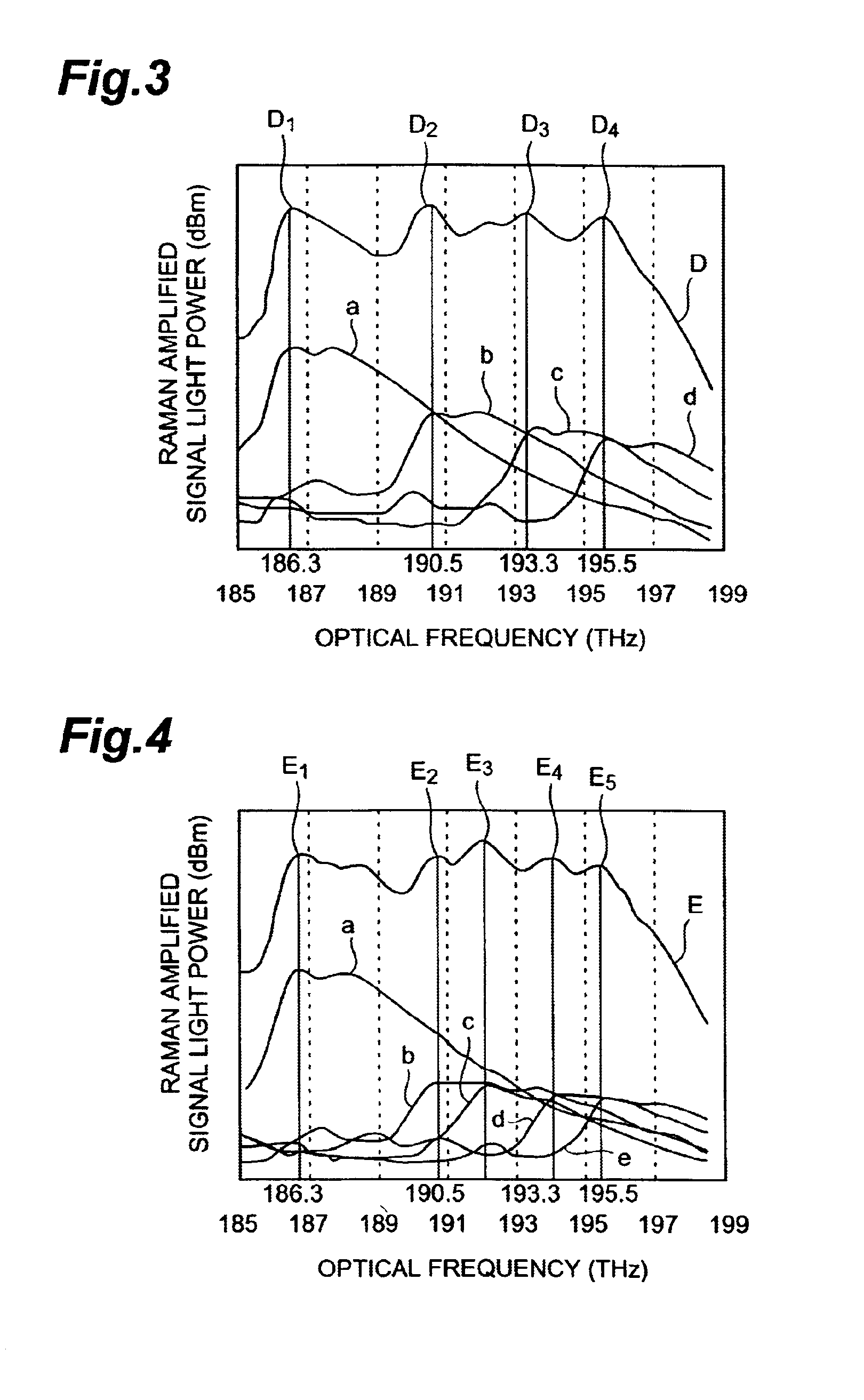
[0084]In the second embodiment, while the controller 13e controls the pumping light source 12a by way of an electric signal line 13f according to the result of detection effected by the photodetector 14, optical frequencies indicating boundaries between optical frequency ranges are determined when dividing the Raman-amplified signal light into optical frequency ranges having a number identical to that of pumping channels. In particular, when an occurrence of a pumping channel having such a weak power that it does not effectively contribute to Raman amplification is detected, the controller 13e changes the optical frequencies indicating the boundaries between the optical frequency ranges by utilizing a pumping channel other than the pumping channel having the weak power according to the result of detection effected by the photodetector.

[0085]FIG. 14A shows Raman gains (Raman-amplified signal light power spectra) obtained when four pumping channels of pumping light are supplied. The r...


PUM

PropertyMeasurementUnit
wavelength bandaaaaaaaaaa

Abstract

The present invention provides a Raman amplifier and the like comprising a structure for keeping the flatness of power spectrum of Raman-amplified signal light. The Raman amplifier comprises an optical fiber for Raman-amplifying a plurality of signal channels of signal light having respective center optical frequencies different from each other; a pumping light supply section for supplying N (N being an integer of 2 or more) pumping channels of pumping light having respective center optical frequencies different from each other to the optical fiber; and a feedback section for detecting a part of the signal light Raman-amplified within the optical fiber when the pumping light is supplied thereto, and controlling the pumping light supply section such that the Raman-amplified signal light has a substantially flat power spectrum with respect to an optical frequency direction according to the result of detection. In particular, the feedback section divides the detected Raman-amplified signal light into N optical frequency ranges defined so as to include respective Raman amplification peaks as optical frequencies lower than respective center optical frequencies of the pumping channels of pumping light by an optical frequency shift of about 15 THz, and controls the pumping light supply section such that the Raman-amplified signal light has a power fluctuation of 2 dB or less in each of thus divided N optical frequency ranges.

Description

BACKGROUND OF THE INVENTION[0001]1. Field of the Invention[0002]The present invention relates to a Raman amplifier for Raman-amplifying a plurality of signal channels of signal light by utilizing Raman scattering effect, a method of controlling the Raman amplifier, and an optical communication system including the Raman amplifier.[0003]2. Related Background Art[0004]For improving the information transmission capability of optical communication systems, the wavelength division multiplexing transmission of signal light has become widespread. Such an optical communication system utilizes optical amplifiers directly amplifying the signal light during the transmission. Here, it is important for the optical amplifiers to attain amplification over a wide wavelength range (optical frequency range) and flatten the power spectrum of amplified signal light in the wavelength range (optical frequency range). Typical optical amplifiers are optical fiber amplifiers, such as those doped with rare-e...

Claims


Application Information

Patent Timeline
Patent Type & Authority Patents(United States)
IPC IPC(8): H04B10/17H04B10/291
CPCH04B10/2916
Inventor INOUE, MASAYUKIKAKUI, MOTOKI
Owner SUMITOMO ELECTRIC IND LTD
Why Eureka
Try Eureka