Engine control device

a control device and engine technology, applied in the direction of electric control, speed sensing governors, instruments, etc., can solve the problems of large fuel consumption, low pump efficiency, large fuel consumption, etc., and achieve the effect of short time, improved pump efficiency, and high responsivity of engine 2

Inactive Publication Date: 2005-10-25
KOMATSU LTD
View PDF6 Cites 83 Cited by
  • Summary
  • Abstract
  • Description
  • Claims
  • Application Information

AI Technical Summary

Benefits of technology

[0106]When the hydraulic equipment load becomes large and the matching point moves from the no-load deceleration point N1 to the high-load rated point V1, the power of the electric motor 4 is added to the power of the engine 2. The time for accelerating the flywheel of the engine 2 becomes short as the engine power is assisted by the power of the electric motor 4, and the movement to the rated point V1 can be made in a short time.
[0107]Therefore, according to the thirteenth aspect of the invention, the responsivity of the engine 2 can be kept high while the pump efficiency is improved.

Problems solved by technology

As described above, according to the conventional engine control method, the engine 2 can be made to follow the hydraulic equipment load with good responsivity but has disadvantages that a fuel consumption rate is large (bad) and pump efficiency is low.
It is apparent from FIG. 14 that the regulation line Fe is equivalent to an area where the fuel consumption is relatively large on the equal fuel consumption curve M. Therefore, the conventional engine control method had a disadvantage that the fuel consumption was large (bad) and not desirable in view of the engine efficiency.
Therefore, the conventional engine control method has a disadvantage that the pump efficiency is low.

Method used


Image

  • Engine control device
  • Engine control device
  • Engine control device

Examples


Embodiment Construction

[0132]Embodiments of the present invention will be described with reference to the accompanying drawings.

[0133]It is assumed in this embodiment that a diesel engine mounted on construction machines such as hydraulic excavators, bulldozers, dump trucks and wheel loaders is controlled.

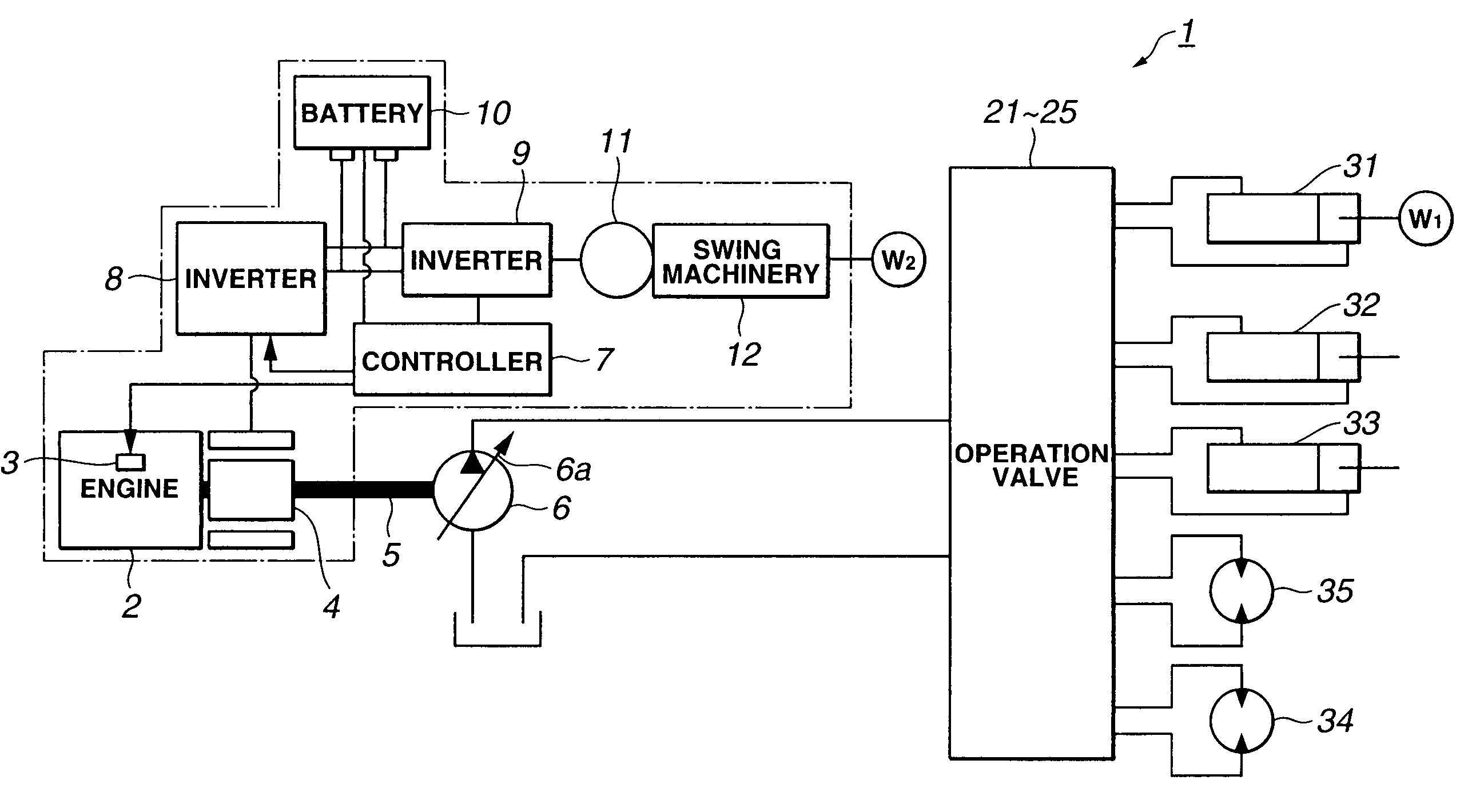
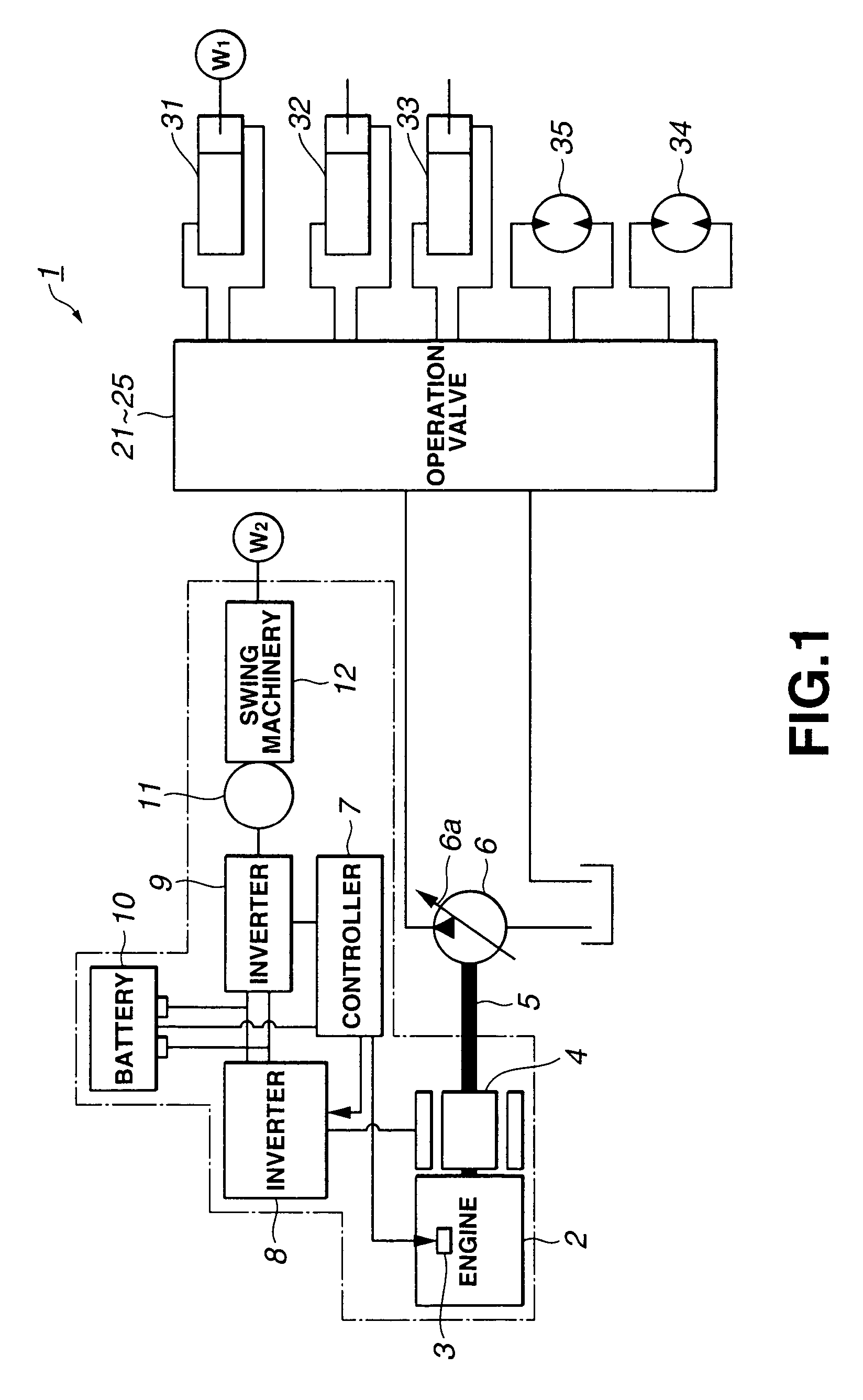
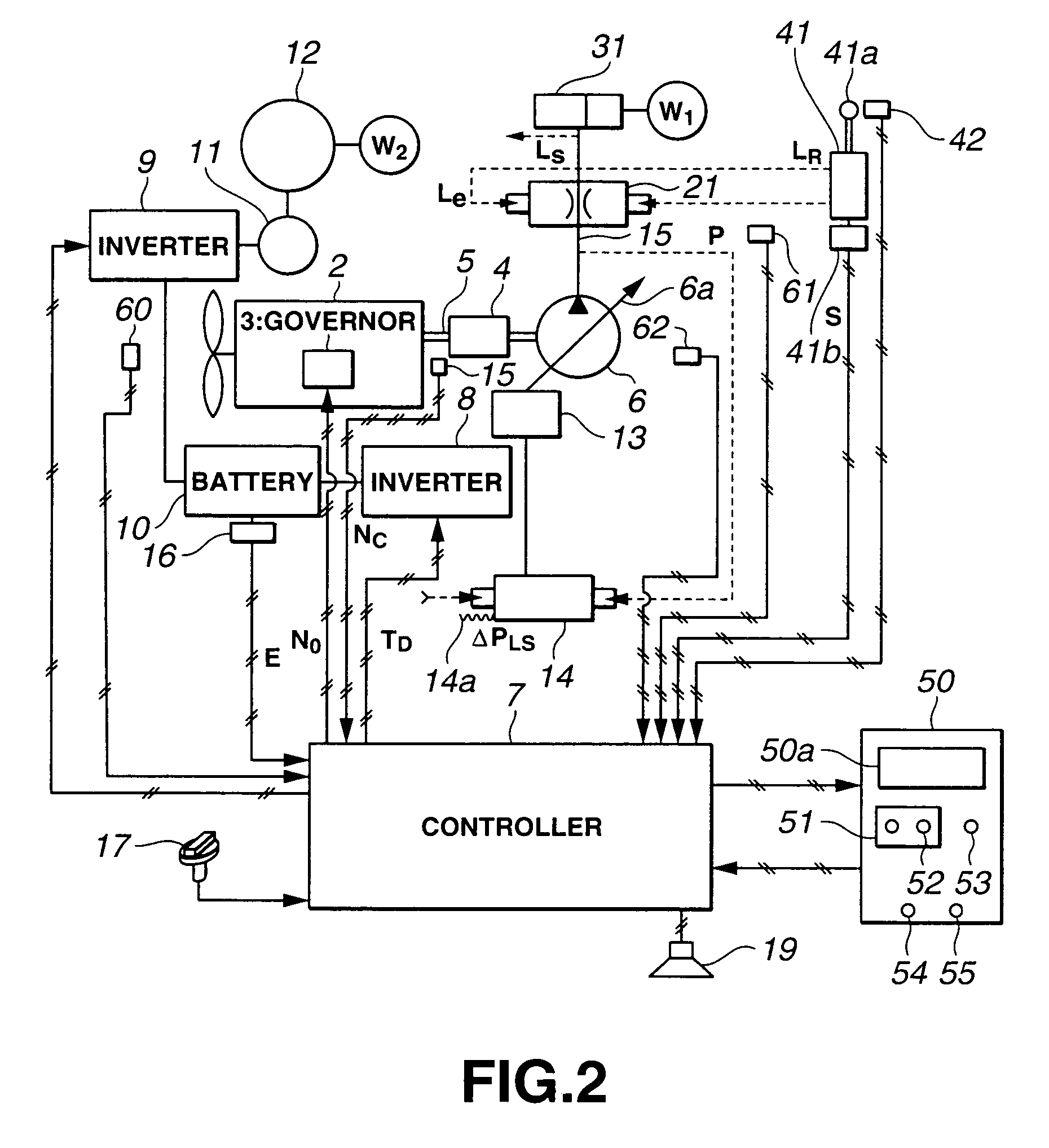
[0134]FIG. 1 shows the whole structure of the construction machine 1 of the embodiment. The construction machine 1 is assumed to be a hydraulic excavator. FIG. 2 shows signals being input to and output from the controller 7 shown in FIG. 1.

[0135]The construction machine 1 is comprised of an upper rotating body W2 and a lower traveling body, and the lower traveling body is comprised of right and left caterpillar belts. A working machine comprising a boom, an arm and a bucket is attached to the vehicle body. The boom hydraulic cylinder 31 is driven to operate a boom W1, the arm hydraulic cylinder 32 is driven to operate the arm, and the bucket hydraulic cylinder 33 is driven to operate the bucket. The hydr...


PUM


Abstract

An engine control device capable of improving engine efficiency by operating the engine in an area where fuel consumption is small (good) while allowing high responsivity of the engine to be maintained. The object can be achieved by operating to match at a point on a target torque line of a torque diagram and operating an electric motor when a matching point moves on the target torque line in a direction in which a load applied to the engine output shaft becomes large.

Description

BACKGROUND OF THE INVENTION[0001]1. Field of the Invention[0002]The present invention relates to an engine control device, and more particularly to an engine control device which is used when hydraulic equipment such as a hydraulic pump is driven by an engine.[0003]2. Description of the Related Art[0004]Construction machines such as hydraulic excavators, bulldozers, dump trucks and wheel loaders have a diesel engine mounted thereon.[0005]The structure of a conventional construction machine 1 will be described briefly with reference to FIG. 1. As shown in FIG. 1, a hydraulic pump 6 is driven by a diesel engine 2 used as a drive source. For the hydraulic pump 6, a variable displacement hydraulic pump is used, and its displacement D (cc / rev) is varied by varying the inclination angle of its swash plate 6a, or the like. Pressure oil discharged with a discharge pressure P and a flow rate Q (cc / min) from the hydraulic pump 6 is supplied to individual hydraulic actuators 31 to 35, e.g., a ...

Claims


Application Information

Patent Timeline
Patent Type & Authority Patents(United States)
IPC IPC(8): B60K6/04B60K6/00F02D45/00B60W10/06B60W10/08B60W20/00F02D29/02F02D29/04F02D41/04
CPCB60K6/485B60W10/06B60W10/08B60W20/00F02D41/1497B60Y2200/25F02D2200/101Y02T10/56Y02T10/6208Y02T10/6226Y02T10/6286F02D2250/18Y02T10/40Y02T10/62B60W2510/06B60W2710/105
Inventor ITOW, KOICHIROHIRAKI, HIKOSABUROUMORINAGA, JUN
Owner KOMATSU LTD
Why Eureka
Try Eureka