
Frost-resistant windmill for use in urban environment

a windmill and urban environment technology, applied in renewable energy generation, greenhouse gas reduction, other chemical processes, etc., can solve the problems that the known design of a windmill power generator cannot meet the conditions, and the windmill power generator cannot be widely accepted in large cities, so as to improve the efficiency of power generation, prevent malfunction, and smooth out the effect of rotational speed fluctuations

Inactive Publication Date: 2005-11-01
BLANK ANATOLY +2
View PDF1 Cites 8 Cited by
  • Summary
  • Abstract
  • Description
  • Claims
  • Application Information

AI Technical Summary

Benefits of technology

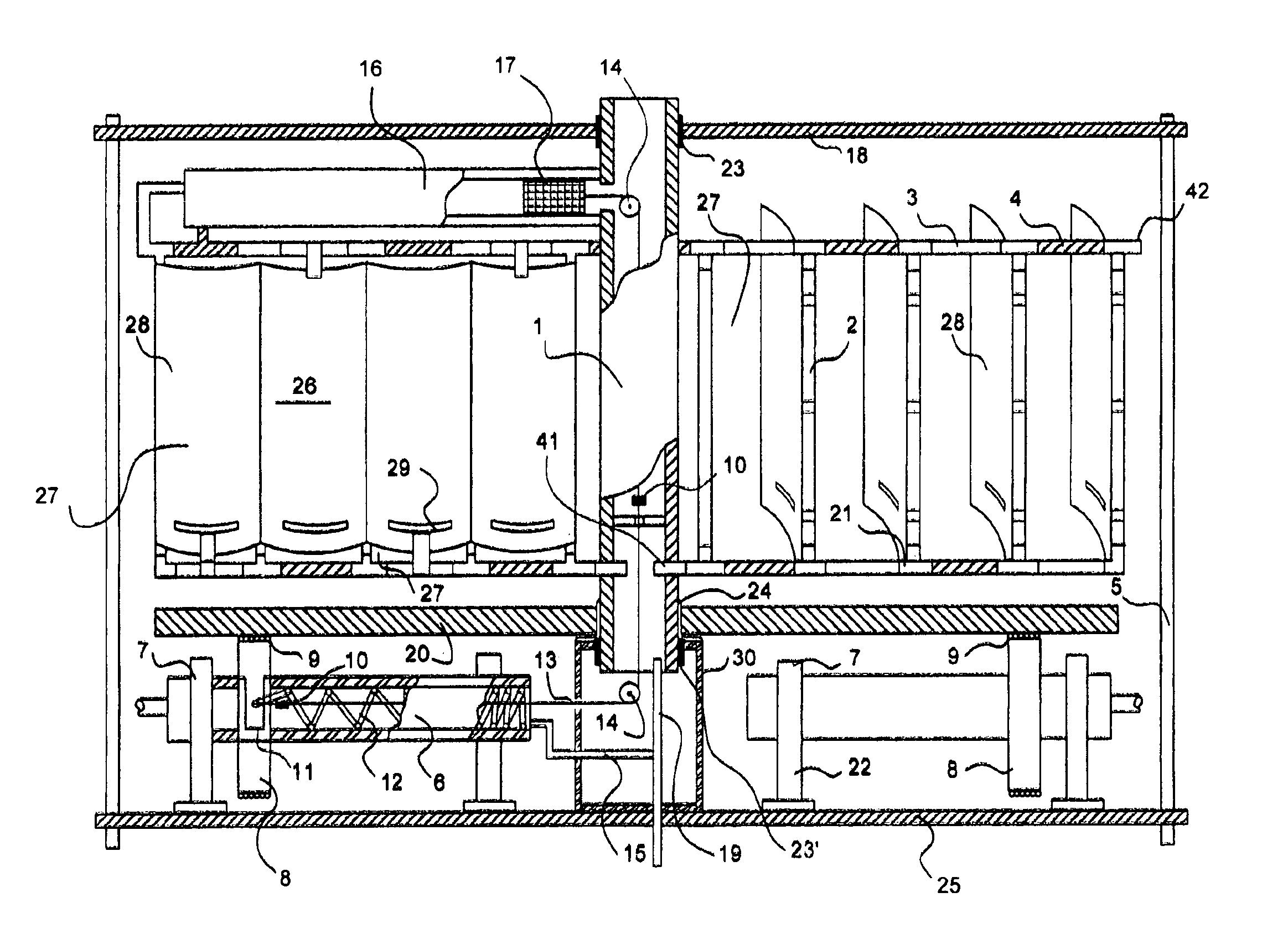
[0009]It is another object of the present invention to provide a windmill equipped with a heating system to prevent malfunction in sub-freezing temperatures.
[0010]It is a further object of the present invention to provide a windmill with speed adjustment means adapted to smooth out fluctuations in the speed of rotation caused by sudden gusts of wind.
[0011]It is yet a further object of the present invention to provide a windmill with increased efficiency of power generation by providing windmill blades having a bottom cutout slit and a wind diverter to direct the wind upwards and create low pressure conditions on the blade backside.
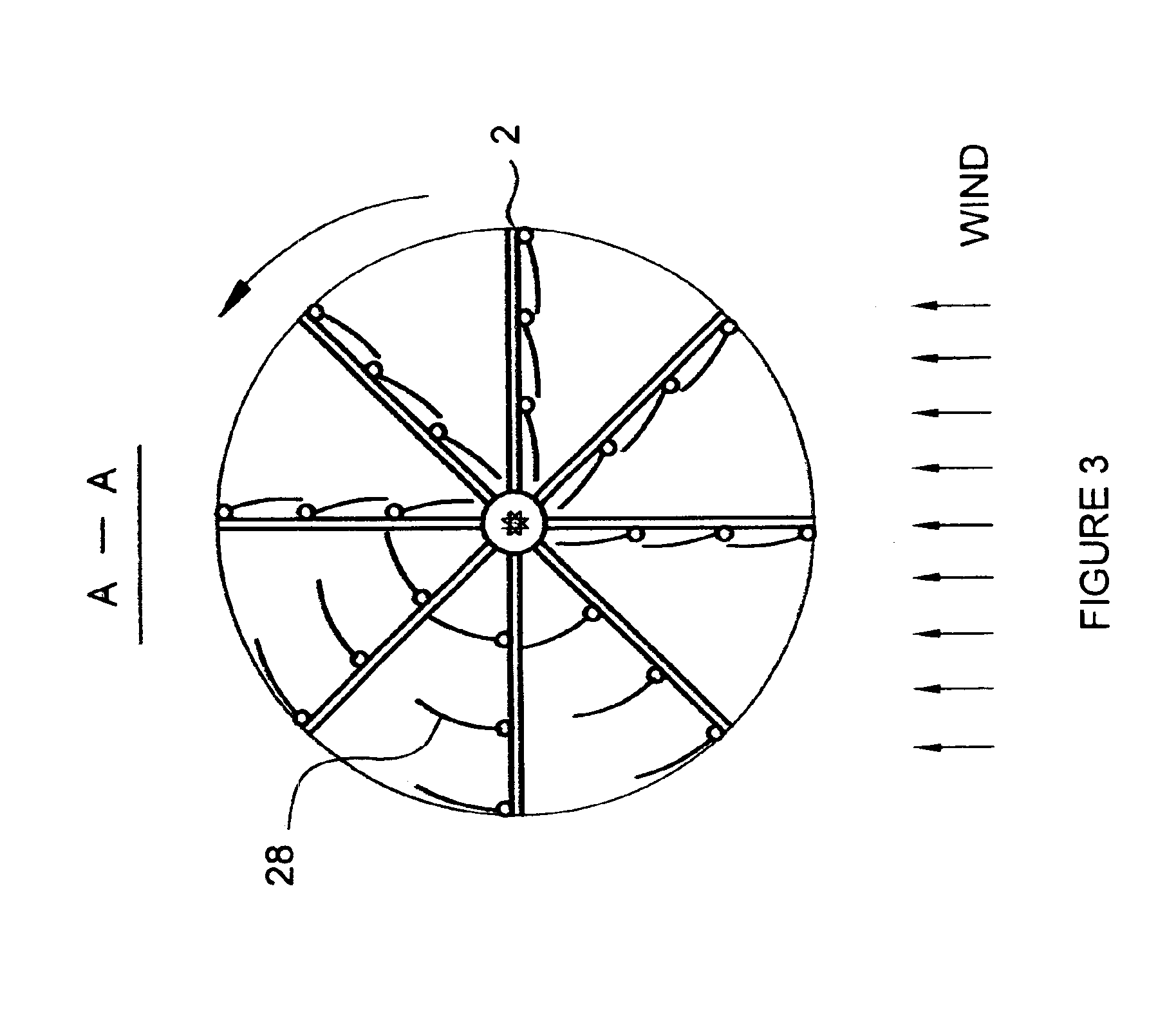
[0012]The windmill of the invention encompasses a vertical shaft with windmill wings extending horizontally therefrom. Each wing is equipped with a partially hollow rectangular blade supporting frame adapted to carry a stream of warm air therein in a serpentine configuration to prevent all movable elements thereof from freezing in winter conditions. Each wing consists of two vanes located opposite each other and attached to the main shaft. Each vane supports a number of blades thereon supported by the rectangular frame. Each blade is attached to the vertical element of the supporting frame of each vane with the ability to turn about ¼ turn away from the wind in passive position and back into being perpendicular to the wind when in its operating position. The blades of one vane are attached as a mirror image of each other to allow rotation in a direction opposite to that of the opposite vane. That way, only one vane is active at one time regardless the direction of the wind. The shaft also carries a horizontal flywheel, which in turn rotates the drive wheels of the electrical generator or another useful load. A centrifugal speed adjustment means are also provided to slow down the rotation of the drive wheels in case of a sudden gust of wind by bringing the drive wheel closer to the center of rotation. The speed adjustment means include a system of pulleys connecting the spring-biased drive wheels to the speed governor weight in the upper portion of the supporting frame. The speed governor weight applies a centrifugal force to the pulleys and therefore to the drive wheel and counteracts the force of the spring to bring the drive wheel to the proper radius from the center of rotation.

Problems solved by technology

In addition, fluctuating demands for electrical power make it necessary to provide supplementary or secondary power supplies to the main electrical power grid of large cities.
However, due to many drawbacks of the known devices, they did not gain widespread acceptance in large cities, despite their commercial success in rural environment.
No known design of a windmill power generator can satisfy the conditions above.

Method used


Image

  • Frost-resistant windmill for use in urban environment
  • Frost-resistant windmill for use in urban environment
  • Frost-resistant windmill for use in urban environment

Examples


Embodiment Construction

[0019]A detailed description of the present invention follows with reference to accompanying drawings in which like elements are indicated by like reference letters and numerals.

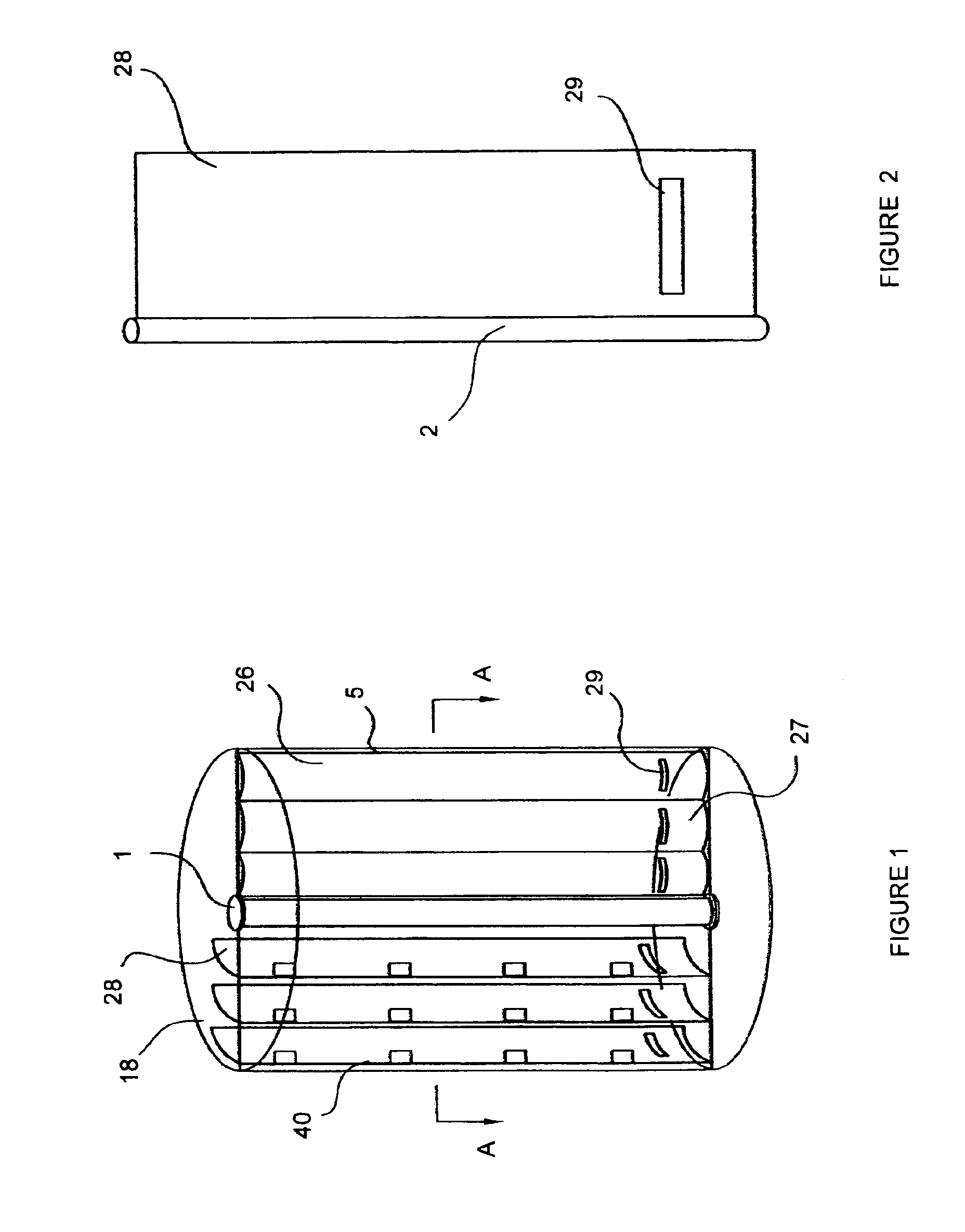
[0020]FIGS. 1 through 5 illustrate the design of the windmill. FIG. 1 shows main hollow vertical shaft 1 carrying a number of wings 26. The main shaft 1 is supported between the lower base plate 25 and the upper base plate 18 connected to each other by a number of peripheral posts 5. Each wing 26 consists of two vanes 27 on both sides of the shaft 1. Each vane 27 includes a supporting frame 40 with one or more vertical peripheral posts 5, each post supporting a vertical blade 28. Free end of each blade 28 covers the adjacent peripheral post 5 so that these blades are arranged to overhang each other, similar to that of fish scales.

[0021]The frame 40 is made of alternating intermittent hollow and solid elements such as hollow and sealed pipes to create an internal serpentine air pathway for introducing of warm...


PUM


Abstract

A frost-resistant windmill is disclosed to provide supplemental power supply for use preferably in large cities. The frame of the windmill carrying a plurality of blades is made hollow defining a serpentine internal air pathway adapted for introduction of warm air from an external source to prevent freezing when used during winter months. A centrifugal speed adjustment system is provided to reduce rotation speed fluctuations of the load drive shaft when strong wind gusts are encountered. A speed adjustment weight is connected to the drive wheel through a cable such that the position of the drive wheel along the radius of the windmill is defined by an equilibrium between the pull force on the cable and the compression force of the spring urging the drive wheel towards the periphery the windmill.

Description

BACKGROUND OF THE INVENTION[0001]The present invention relates generally to windmill energy generators. More particularly, the device of the invention utilizes a centrifugal speed adjustment means to stabilize the speed of rotation of the windmill in conditions of various strength winds. Further, the windmill of the invention utilizes a heating system to prevent malfunctions of the device when operating in freezing temperatures. The windmill of the invention can be most advantageously used in urban environment.[0002]It is well established that modern cities can benefit from renewable source power supplies. In addition, fluctuating demands for electrical power make it necessary to provide supplementary or secondary power supplies to the main electrical power grid of large cities. Preferably, such secondary power supply sources should be located close to large power consumers. They should be connected to the existing power grids to provide additional energy as required. Windmills have...

Claims


Application Information

Patent Timeline
IPC IPC(8): F03D3/06F03D3/00
CPCF03D3/067F03D11/0025F05B2260/72Y02B10/30Y02E10/74Y10S415/907Y10S416/06F03D80/40
Inventor BLANK, ANATOLYBLANK, EMILBLANK, LEONID
Owner BLANK ANATOLY
Learn More