Liquid crystal display device for preventing and afterimage

a liquid crystal display and afterimage technology, applied in the field can solve the problems of reducing the long-term reliability of liquid crystal materials, affecting the reliability of liquid crystal display devices, so as to prolong the life of liquid crystals and improve reliability. , the effect of shortening the tim

Inactive Publication Date: 2005-11-01
VISTA PEAK VENTURES LLC
View PDF31 Cites 31 Cited by
  • Summary
  • Abstract
  • Description
  • Claims
  • Application Information

AI Technical Summary

Benefits of technology

[0017]It is therefore an object of the present invention to provide the liquid crystal display device which detects absence of an input signal, and forcibly discharges the charge from the liquid crystal capacitance to shorten the time for which the direct current is applied, thereby preventing the occurrence of the afterimage, lengthening the life of the liquid crystal, and improving the reliability, and the method for driving the same.

Problems solved by technology

However, when the charge is kept in the liquid crystal capacitance for a long time, an afterimage may be produced, the quality of the display and the reliability in use for years may be degraded.
That is, the direct current is applied to the liquid crystal, decreasing the long-term reliability of the liquid crystal material, and causing the afterimage.
In this case, only the liquid crystal display device cannot be turned off.
Even when the conventional liquid crystal display device, which can discharge the charge from the liquid crystal capacitance at the time of turning off the power supply, is applied to the FA, the charge stored in the liquid crystal capacitance cannot be forcibly discharged.
As mentioned above, even in the conventional liquid crystal display device disclosed in Japanese Patent No. 2655328, as the power supply is repeatedly turned on and off, the ionizable material is stacked on the electrode, the afterimages, or stains are produced, decreasing the life of the liquid crystal, and the reliability in use for years.

Method used


Image

  • Liquid crystal display device for preventing and afterimage
  • Liquid crystal display device for preventing and afterimage
  • Liquid crystal display device for preventing and afterimage

Examples


Embodiment Construction

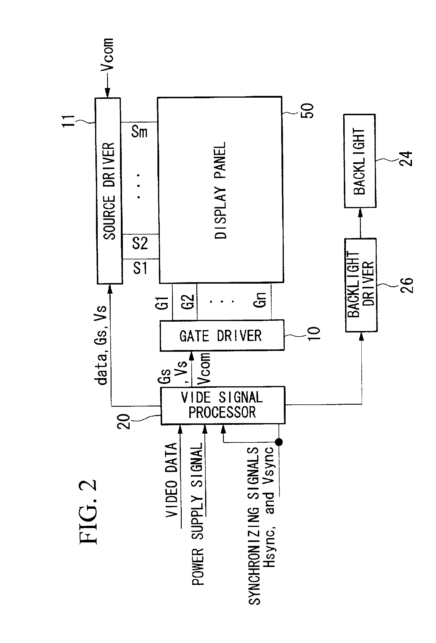
[0038]The embodiment of the present invention will be explained with reference to the figures. FIG. 2 is a block diagram schematically showing the entire structure of the IPS (in-plane-switching) type liquid crystal display device, FIG. 4 is a circuit diagram showing the structure of a unit pixel of a display panel 50, and FIG. 5 is a diagram showing the structure of a unit pixel of the display panel 50.

[0039]In FIG. 4, reference character CL denotes a liquid crystal capacitance equivalent to a liquid crystal capacitance. Reference character RL denotes a liquid crystal resistance. The parallel circuit of the liquid crystal capacitance CL and a liquid crystal resistance RL is connected through a capacitor C1 to a pixel electrode 74, and is connected through a capacitor C2 to a common electrode 76. The pixel electrode 74 is connected to a source of a thin film transistor (TFT) 72, and the drain of the thin film transistor 72 is connected to a data line 80 for controlling a voltage to ...


PUM

PropertyMeasurementUnit
timeaaaaaaaaaa
timeaaaaaaaaaa
electric potentialaaaaaaaaaa

Abstract

The liquid crystal display device includes pixel electrodes; a common electrode; a plurality of data lines and a plurality of gate lines intersecting each other; a plurality of switchers for the pixel electrodes for supplying signals from the data lines to the pixel electrodes; a gate line driver for scanning the gate lines; a data line driver for driving the data lines in accordance with the gradation to be displayed; and a controller for controlling the gate line driver and the data line driver. The controller includes a signal absence detector for detecting that no signal has been input to the liquid crystal display device. The controller outputs a signal to the gate line driver to make all the gate lines active for a predetermined time after the signal absence detector detects that no signal has been input. The controller outputs a signal to the data line driver to supply an electric potential, applied to the common electrode, to all the data lines for the predetermined time.

Description

BACKGROUND OF THE INVENTION[0001]1. Field of the Invention[0002]The present invention relates to a liquid crystal display device which improves the problem of an afterimage, and a method for driving the same.[0003]2. Description of the Related Art[0004]When a user stops using and turns off a conventional liquid display device, the device is shut down without any operation for clearing the image on the display. The supply of various signals (scanning line driving signals, data line driving signals, or the like) to the liquid crystal display panel is stopped, and the paths for externally discharging the charge from the liquid crystal capacitance of the liquid crystal display panel is blocked. The charge then gradually decreases because of self-discharge, so that the displayed image is gradually cleared.[0005]However, when the charge is kept in the liquid crystal capacitance for a long time, an afterimage may be produced, the quality of the display and the reliability in use for years ...

Claims


Application Information

Patent Timeline
Patent Type & Authority Patents(United States)
IPC IPC(8): G02F1/133G02F1/13G09G3/20G09G3/36G09G5/00
CPCG09G3/3648G09G3/3677G09G3/3688G09G5/006G09G2310/0245G02F1/133
Inventor KUSANAGI, TOMOHIRO
Owner VISTA PEAK VENTURES LLC
Why Eureka
Try Eureka