System for sealing off a gap

Inactive Publication Date: 2005-11-08
SIEMENS AG
View PDF12 Cites 18 Cited by
  • Summary
  • Abstract
  • Description
  • Claims
  • Application Information

AI Technical Summary

Benefits of technology

[0008]An object of an embodiment of the present invention is to reduce the quantity of working medium flowing past the turbine bla

Problems solved by technology

However, both in the known labyrinth seals and in the arrangement according to U.S. Pat. No. 4,177,0

Method used


Image

  • System for sealing off a gap
  • System for sealing off a gap
  • System for sealing off a gap

Examples


Example

[0023]Parts corresponding to one another are provided with the same designations in all the figures.

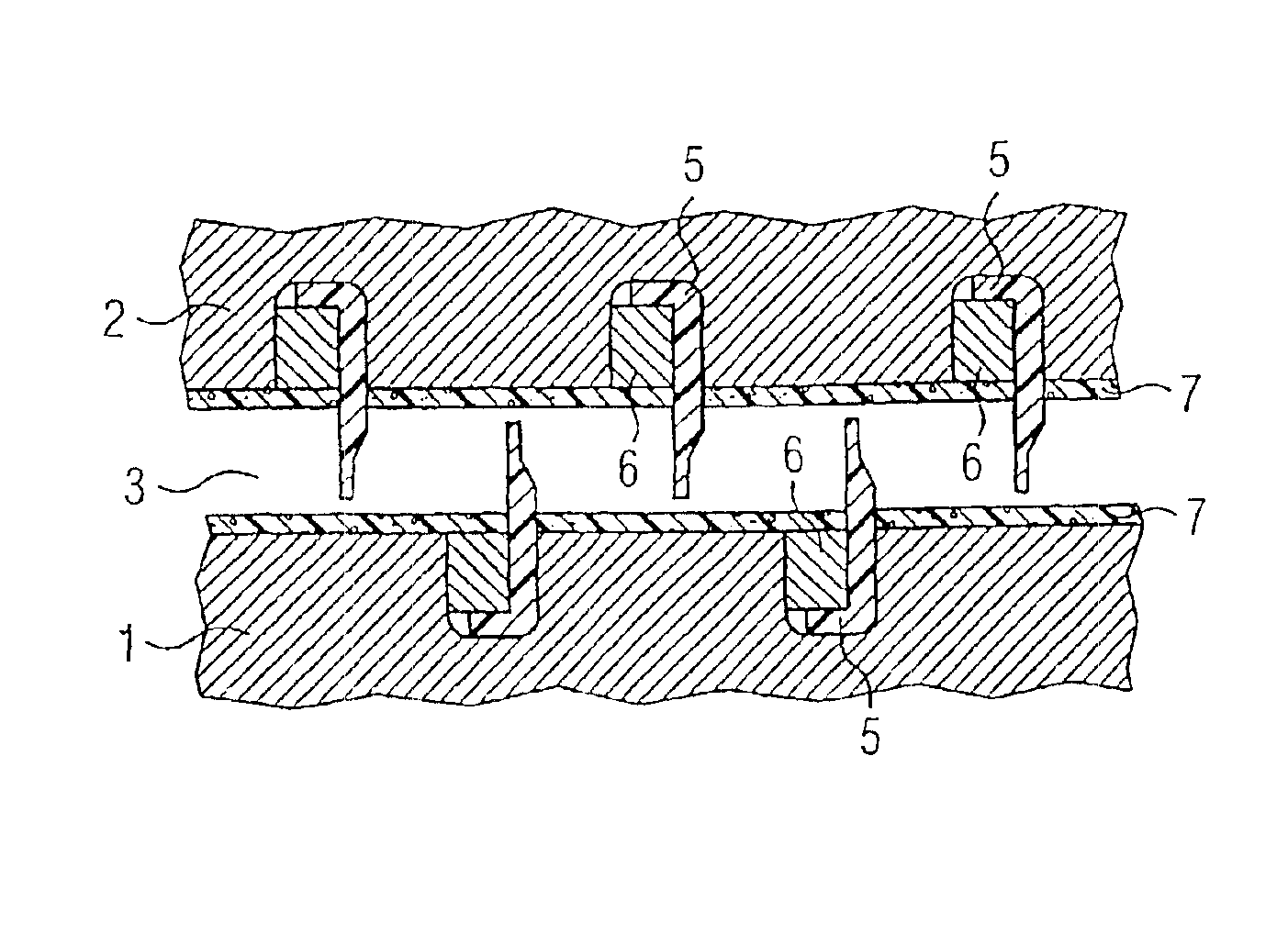
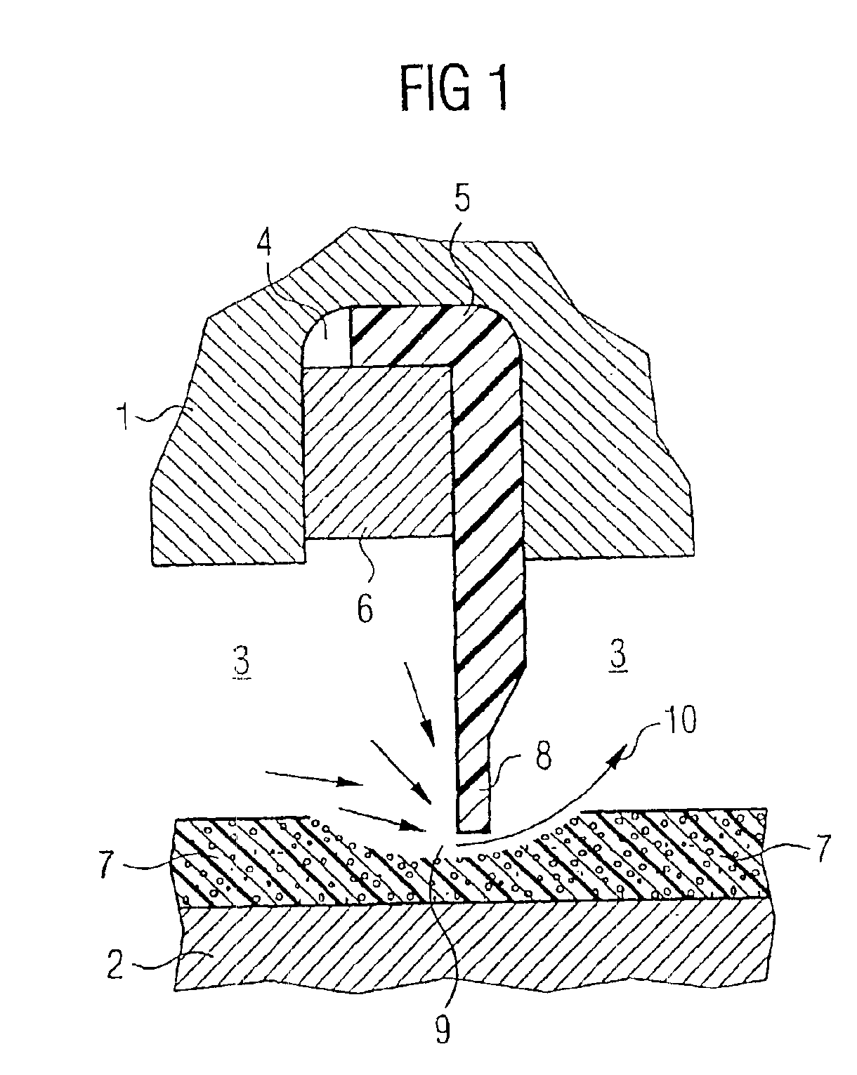
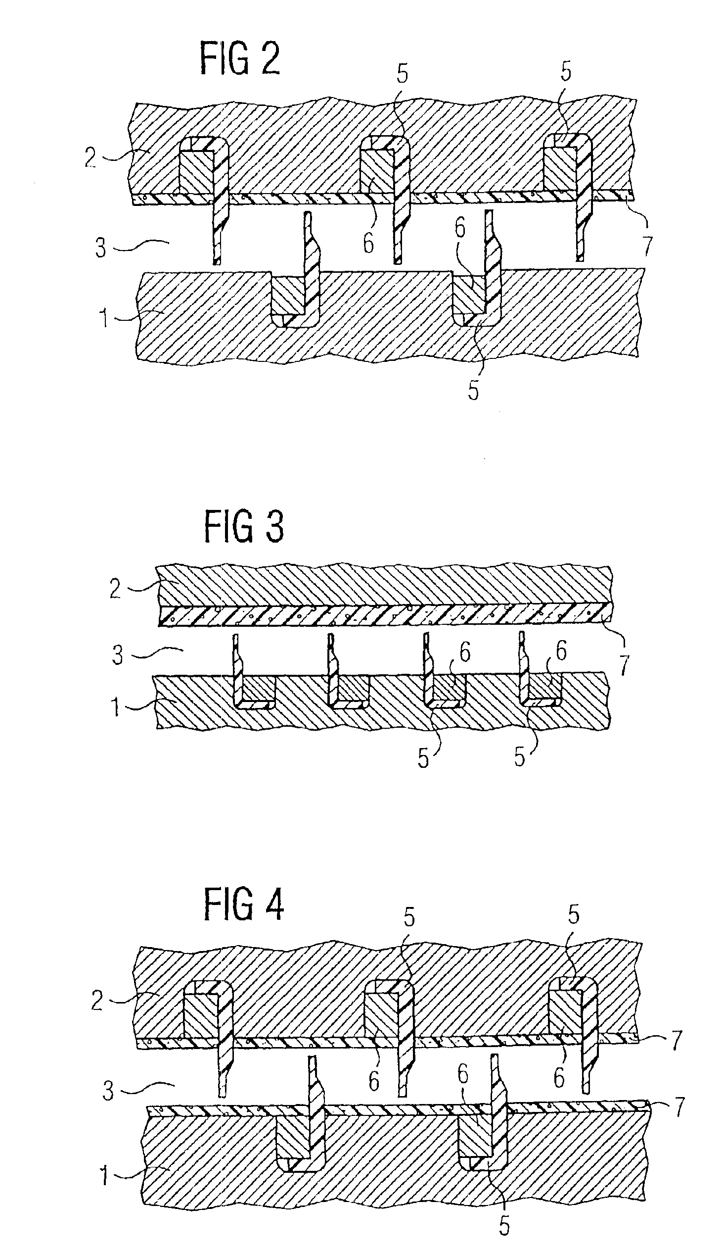
[0024]In FIG. 1, two components 1 and 2 of a steam turbine (not shown in any more detail) form a gap 3 up to several millimeters wide, which is sealed off from a steam flow. The component 1 is preferably a rotor part movable in the operating state and has a groove 4 for accommodating a sealing strip 5 serving as sealing lip. The sealing strip 5 is L-shaped in cross section and rests with its leg, which is shorter in cross section, on the base of the groove 4. The sealing strip 5 includes one or more sections complementing one another in the circumferential direction to form a ring and is secured in the groove 4 by a calking wire 6.

[0025]The component 2 opposite the component 1 on the other side of the gap 3 is preferably stationary in the operating state and has a coating designed as a grazing layer 7. The coating may have a thickness corresponding to 0.5 to 0.1 times the width of the...


PUM


Abstract

In fluid machines frequently gaps between movable and stationary structural parts have been sealed off. Frequently so-called labyrinth packings are used, whereby sealing strips brush against the opposite structural part. To this end, a brush layer is configured as a porous coating that can be detached from the opposite structural part. The inventive system can be advantageously used in virtually any fluid machines.

Description

[0001]This application is the national phase under 35 U.S.C. § 371 of PCT International Application No. PCT / EP01 / 04576 which has an International filing date of Apr. 23, 2001, which designated the United States of America and which claims priority on European Patent Application number 001 09 543.9 filed May 4, 2000, the entire contents of which are hereby incorporated herein by reference.FIELD OF THE INVENTION[0002]The present invention generally relates to an arrangement for a fluid-flow machine. In particular, the present invention generally relates to a steam turbine, for sealing a gap between a movable component and a stationary component, of which one carries a grazing layer on a surface flanking the gap.BACKGROUND OF THE INVENTION[0003]In machines for treating and processing flowing, liquid and / or gaseous media, gaps between movable and stationary components are often to be sealed off from the flowing medium. This also applies in particular to turbines to which steam is admitt...

Claims


Application Information

Patent Timeline
IPC IPC(8): F01D11/00F01D11/08F01D11/12F01D11/02F16J15/447
CPCF01D11/02F01D11/122
Inventor WIEGHARDT, KAI
Owner SIEMENS AG
Why Eureka
Try Eureka