Multi-range parallel-hybrid continuously variable transmission

a transmission and multi-range technology, applied in the direction of electric propulsion mounting, transportation and packaging, gearing, etc., can solve the problems of reducing the performance level of the vehicle, determining the performance limits of the vehicle, and less applicable to large vehicles such as trucks, so as to achieve a high degree of flexibility and improve the efficiency of the vehicl

Active Publication Date: 2005-11-08
BAE SYSTEMS CONTROLS INC
View PDF13 Cites 76 Cited by
  • Summary
  • Abstract
  • Description
  • Claims
  • Application Information

AI Technical Summary

Benefits of technology

[0024]Furthermore, the hybrid transmission according to an aspect of the invention provides for selective and individual control of the two motor/generator units to provide for routing power in different directions for different situations, including the capability of starting the internal combustion engine using power from one or both motor/generators, battery charging from the engine, regenerative braki

Problems solved by technology

When charged, the energy storage means may provide all the power used to move the vehicle, but only for a limited time and perhaps at reduced performance levels.
One drawback that is inherent in the configuration, however, is that the electric machine(s) that finally couple to the driving elements, determine the limits of performance of the vehicle.
Small hybrid automobiles may use, for example, a Van Doorne belt CVT configuration, which may be effective for smaller vehicles but is less applicable to large vehicles such as trucks,

Method used


Image

  • Multi-range parallel-hybrid continuously variable transmission
  • Multi-range parallel-hybrid continuously variable transmission
  • Multi-range parallel-hybrid continuously variable transmission

Examples


Embodiment Construction

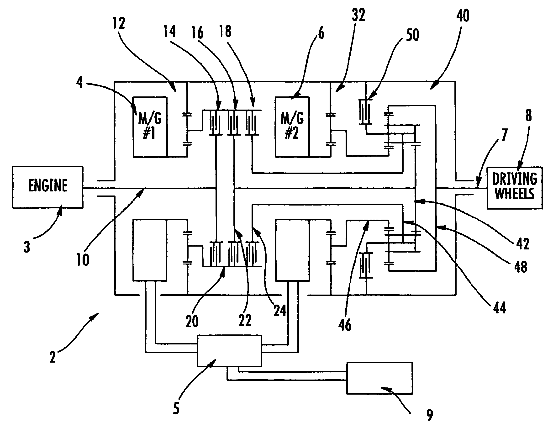
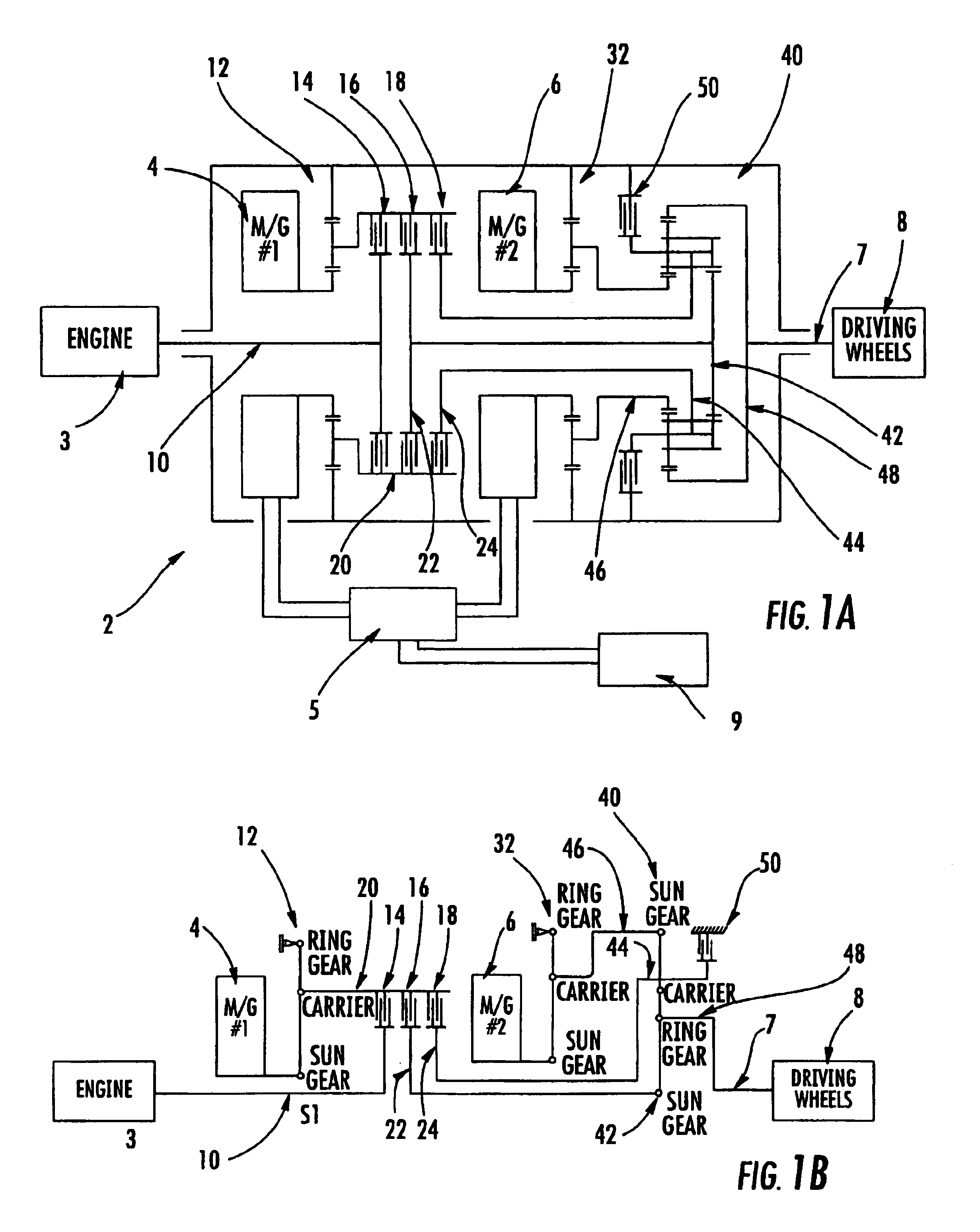
[0031]Referring to FIG. 1a illustrating a first embodiment of the present invention, a multi-range parallel-hybrid continuously variable transmission, generally indicated by reference number 2, includes an input shaft 10 receiving power from a prime mover 3 to the transmission 2. The prime mover can be an internal combustion engine or another device capable of imparting rotational power to shaft 10. A first electrical motor / generator unit 4 (labeled M / G #1) is concentrically located relative to the input shaft 10 such that the input shaft passes through the first motor / generator 4. The first motor / generator is capable of generating and receiving power and operates in either a clockwise or counterclockwise rotational direction.

[0032]A first planetary gear set 12 has its sun gear connected to the rotating rotor of the first motor / generator unit (4). The rotor speed of rotation is increased when driven by the planet gear carrier of the first planetary gear set, when the ring gear of th...


PUM


Abstract

A parallel-hybrid transmission has one or more electrical motor/generator units, at least one of which moves in an anti-engine-wise direction in certain operational modes. The motor/generators are coaxially or concentrically arranged with the transmission input and output shafts via planetary gear sets. Associated clutch closures selectively couple power to and from the sun gears and planetary carriers of the gear sets through a complex planetary gear configuration such as a Ravigneaux gear set, for switching between certain operational modes. The clutch and brake operations selectively achieve multiple ratio range operations including engine starting under electric power, high torque acceleration from a standstill, regenerative deceleration (braking), multiple ratio range operation, load sharing, rotation-matched step-less shifting and combined or individual continuously variable combustion engine and electric motor and/or generation modes.

Description

CROSS REFERENCE TO RELATED APPLICATION[0001]This application claims the priority of U.S. Provisional Patent Application Ser. No. 60 / 412,257, filed Sep. 23, 2002.FIELD OF THE INVENTION[0002]The invention relates to multiple-ratio range continuously-variable transmissions, for example for use with electric motor / generator units in combination with internal combustion engines, typically for motor vehicle drive trains.BACKGROUND OF THE INVENTION[0003]Arrangements using multiple sources of power for vehicles, such as electric motor and internal combustion-powered vehicles, often have aspects that fall into one of two general categories, namely those in which the power sources are serially arranged, and those in which they are at least partly parallel. A multiple or hybrid power source, for example, may comprise an internal combustion engine and one or more electric rotating machines operable as motors or as generators in different conditions. These power sources may drive one another ser...

Claims


Application Information

Patent Timeline
IPC IPC(8): B60K6/04B60K6/00F16H3/72F16H3/44B60K1/02B60K1/00B60K6/365B60K6/445B60W10/02B60W10/08B60W20/00
CPCB60K6/365B60K6/44B60K6/445B60W10/02B60W10/08F16H3/728B60K1/02B60W20/00F16H2037/088F16H2037/103F16H2037/107Y02T10/623Y02T10/6239Y02T10/62B60W10/26B60W2050/004
Inventor LARKIN, ROBERT P.
Owner BAE SYSTEMS CONTROLS INC
Why Eureka
Try Eureka