Joint replacement prosthesis component with non linear insert

a joint replacement and component technology, applied in the field of orthopaedics, can solve the problems of limiting the load carrying capacity of this configuration, not providing the required strength to support and reinforce the spine, and not allowing for a straight rod. achieve the effect of increasing the load

Inactive Publication Date: 2005-11-08
DEPUY PROD INC
View PDF41 Cites 43 Cited by
  • Summary
  • Abstract
  • Description
  • Claims
  • Application Information

AI Technical Summary

Benefits of technology

[0026]Attempts have been made to reinforce polyethylene bearings. One such attempt is that as shown in U.S. Pat. No. 5,989,472 Ashby, et al, incorporated herein by reference. The polyethylene bearing in Ashby includes a reinforcement feature for bone attachment. The reinforcement feature is to assist in eliminating motion between the polyethylene and the metal backing.
[0028]The technical advantages of the present invention include the ability to allow for the desired kinematics of the knee during a full range of motion for patients in whom the cruciate ligaments have either been severely damaged, removed, or sacrificed. In such conditions the femoral and tibial components of the knee prosthesis need to be constrained with respect to each other by use of, for example, a spine and cam mechanism.

Problems solved by technology

Unfortunately, this design does not allow for a straight rod, commonly employed for reinforcement of tibial bearing inserts, to be used.
The polymer strength would then limit the load carrying capacity of this configuration.
Such a configuration may not provide the required strength to sufficiently support and reinforce the spine.

Method used


Image

  • Joint replacement prosthesis component with non linear insert
  • Joint replacement prosthesis component with non linear insert
  • Joint replacement prosthesis component with non linear insert

Examples


Embodiment Construction

[0052]Embodiments of the present invention and the advantages thereof are best understood by referring to the following descriptions and drawings, wherein like numerals are used for like and corresponding parts of the drawings.

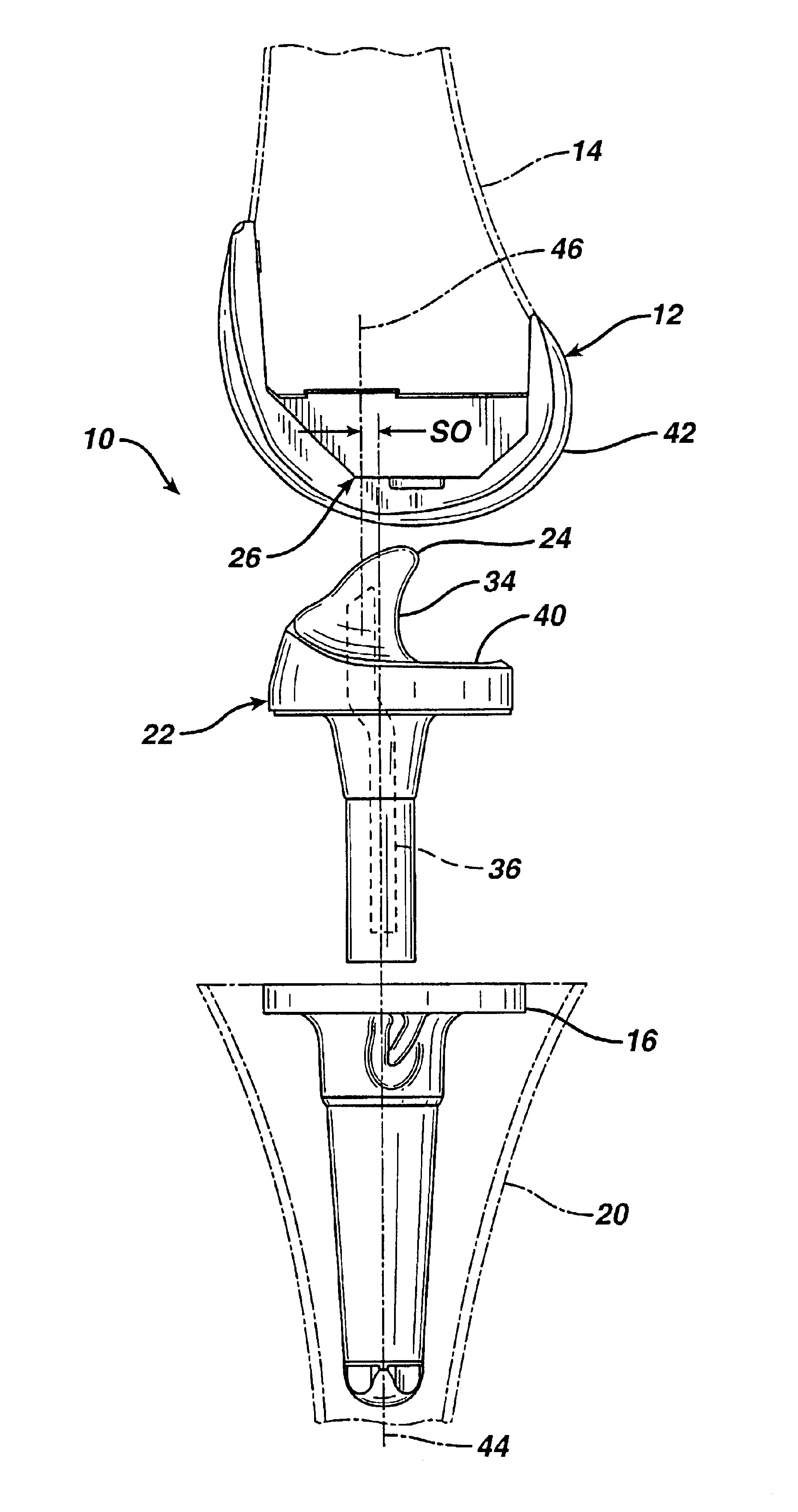
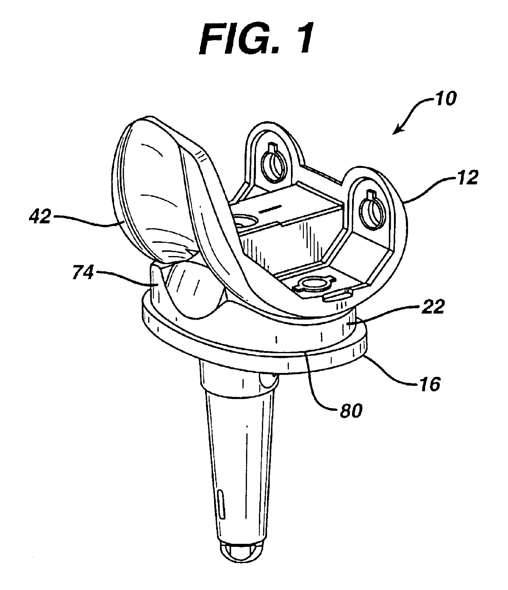
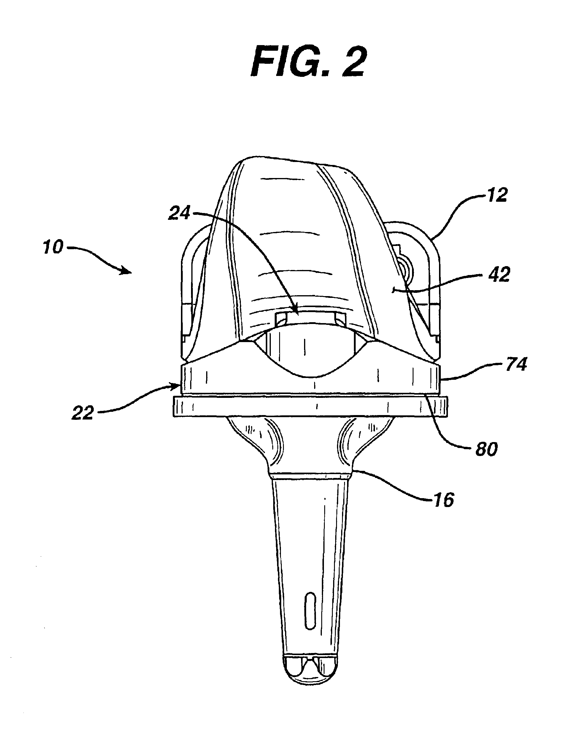
[0053]According to the present invention and referring now to FIG. 8, a joint prosthesis in the form of knee prosthesis 10 is shown. The knee prosthesis 10 includes a femoral component or first component 12 for attachment to femur or first long bone 14. The prosthesis 10 further includes a tibial tray or second component 16 for attachment to tibia or second long bone 20. The femoral component 12 and the tibial component 16 are shown in greater detail in FIGS. 1-9 and 16-19. The femoral component 12 and the tibial component 16 are made of any suitable durable material which is biocompatible with the human anatomy. The femoral component 12 and the tibial component 16 may, for example, be made of a cobalt alloy, for example, cobalt-chromium-molybdenum, a titanium...


PUM

PropertyMeasurementUnit
molecular weightaaaaaaaaaa
structureaaaaaaaaaa
rotationaaaaaaaaaa

Abstract

According to one embodiment of the present invention, there is provided a joint prosthesis (10) having a first component (12) for cooperation with a first long bone (14) and a second component (16) for cooperation with a second long bone (20). The joint prosthesis (10) further includes a bearing component (22) positionable between the first component (12) and the second component (16) and cooperable with the first component (12) and the second component (16). The bearing component (22) includes a reinforcing component (36) having a first portion (54) defining a first centerline (50) and having a second portion (56) defining a second centerline (52). The first centerline (50) and the second centerline (52) are non-coincidental. The bearing component (22) includes a polymeric material (112) surrounding the reinforcing component (36) and molded to the reinforcing component (36). The bearing component (22) defines a first peripheral region (34) adjacent the first portion (54) of the reinforcing component (36) and a second peripheral region (82) adjacent the second portion (56) of the reinforcing component(36). The first peripheral region (34) cooperates with first component (12) and the second peripheral region (82) cooperates with the second component (16).

Description

CROSS REFERENCE TO U.S. PROVISIONAL PATENT APPLICATION[0001]This application is a Utility Application based upon U.S. Provisional Patent Application, Ser. No. 60 / 302,098 filed Jun. 30, 2001, entitled JOINT REPLACEMENT PROSTHESIS COMPONENT WITH NON LINEAR INSERT.CROSS-REFERENCE TO RELATED APPLICATIONS[0002]Cross reference is made to the following applications:[0003]DEP 677 titled “JOINT PROSTHESIS MOLDING METHOD AND DIE FOR PREFORMING THE SAME” and DEP 678 titled “SURFACE STERILIZABLE JOINT REPLACEMENT PROSTHESIS COMPONENT WITH INSERT” filed concurrently herewith which are incorporated herein by reference.TECHNICAL FIELD OF THE INVENTION[0004]The present invention relates generally to the field of orthopaedics, and more particularly, to an implant for use in joint arthroplasty.BACKGROUND OF THE INVENTION[0005]The invention relates to joint prostheses. More particularly, the invention is directed to tibial components of knee joint prostheses that can be configured to be either rotatab...

Claims


Application Information

Patent Timeline
Patent Type & Authority Patents(United States)
IPC IPC(8): A61F2/30A61F2/38B29C43/18B29C43/00A61F2/00A61L27/16
CPCA61F2/30942A61F2/3868A61F2/3886B29C43/006B29C43/18A61F2002/30364A61F2002/30398A61F2002/30604A61F2002/30957A61F2220/0025A61F2220/0033A61F2310/00017A61F2310/00023A61F2310/00029B29L2031/7532
Inventor GUNDLAPALLI, RAMA RAO V.HELDRETH, MARKBURSTEIN, ALBERT
Owner DEPUY PROD INC
Why Eureka
Try Eureka