Process for manufacturing a read head

a technology of read head and manufacturing process, which is applied in the field of gmr recording head, can solve the problems of large bias point shift due to sense current field, difficult to obtain controllable bias point, and significant increase in the resistance of the entire structur

Inactive Publication Date: 2005-11-08
HEADWAY TECH INC
View PDF7 Cites 1 Cited by
  • Summary
  • Abstract
  • Description
  • Claims
  • Application Information

AI Technical Summary

Benefits of technology

[0013]It has been an object of the present invention to provide a spin-filter synthetic antiferromagnetic bottom spin valve that is suitable for ultra-high density magnetic recording applications.

Problems solved by technology

However, once these electrons ‘switch sides’, they are immediately subject to increased scattering, thereby becoming unlikely to return to their original side, the overall result being a significant increase in the resistance of the entire structure.
However, as the free layer thickness decreases, it becomes difficult to obtain a controllable bias point, high GMR ratio and good magnetic softness all at the same time.
Synthetic antiferromagnets (SyAF) are known to reduce magneto-static fields in a pinned layer, but a large bias point shift due to sense current fields remains a problem for practical use of an ultra-thin free layer.
The problem with the abutted junction is the existence of a “dead zone” at the sensor ends.

Method used


Image

  • Process for manufacturing a read head
  • Process for manufacturing a read head
  • Process for manufacturing a read head

Examples


experimental verification

of the Invention

[0042]For comparison purposes, SF-SyAF top spin valves having:NiCr / Cu / NiFe+CoFe (free layer) / Cu / CoFe1 / Ru / CoFe2 / MnPt / NiCr configurations with equivalent layer thicknesses were also made.

[0043]To characterize free layer anisotropy, free layer structures made of 55 NiCr / 20 Cu / 2 CoFe-34 NiFe / 15 Cu / TaO / Al2O3 and 55 NiCr / 15 Cu / 34 NiFe-2 CoFe / 20 Cu / NiCr, respectively (where all numbers are thicknesses in Angstroms), for the bottom and top SFSV were also studied.

[0044]After forming free layer and GMR stacks, the deposited structures were first given a standard 6000 Oe transverse field 280° C.-5 hrs annealing. The high field annealing set up the pinned layer direction. After removing Al2O3 capping by wet etching, the GMR and the free layer stacks, were further given a low field (100 Oe) 250° C.-5 hrs annealing to reset the free layer in the sensor direction. This low field annealing was used to simulate the exchange bias annealing process.

[0045]Comparisons of the top and bott...


PUM

PropertyMeasurementUnit
temperatureaaaaaaaaaa
magnetic fluxaaaaaaaaaa

Abstract

A high performance specular free layer bottom spin valve is disclosed. This structure made up the following layers: NiCr / MnPt / CoFe / Ru / CoFe / Cu / free layer / Cu / Ta or TaO / Al2O3. A key feature is that the free layer is made of a very thin CoFe / NiFe composite layer. Experimental data confirming the effectiveness of this structure is provided, together with a method for manufacturing it and, additionally, its longitudinal bias leads.

Description

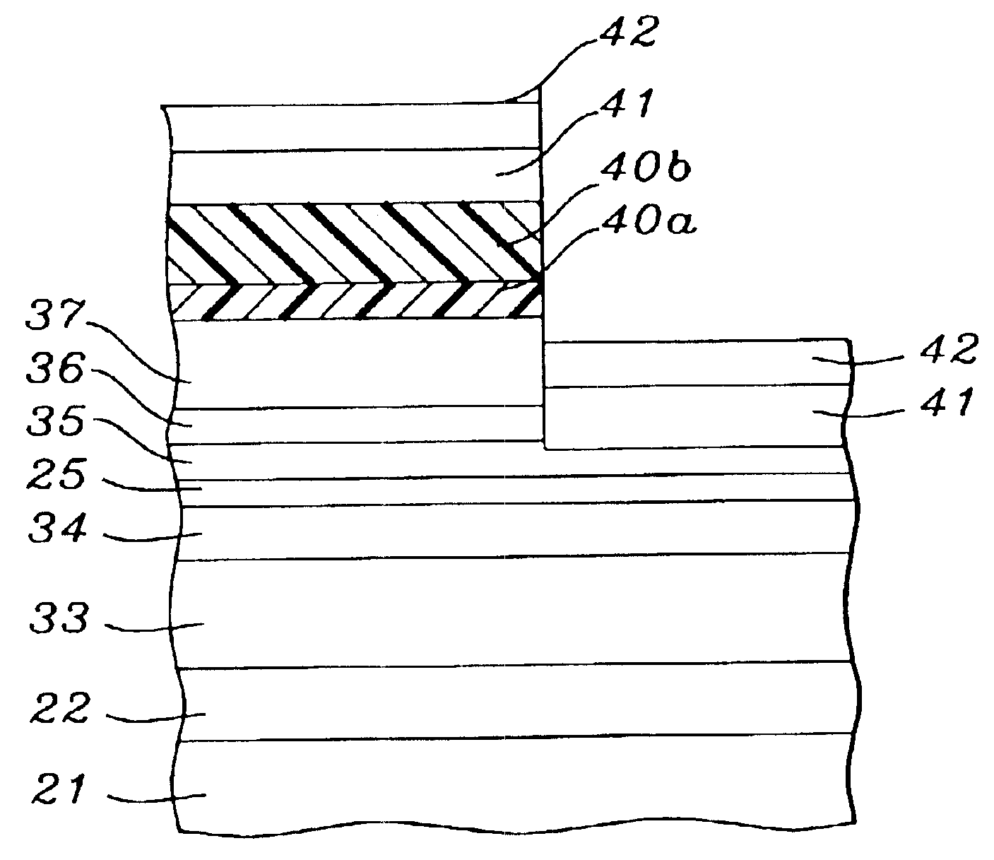
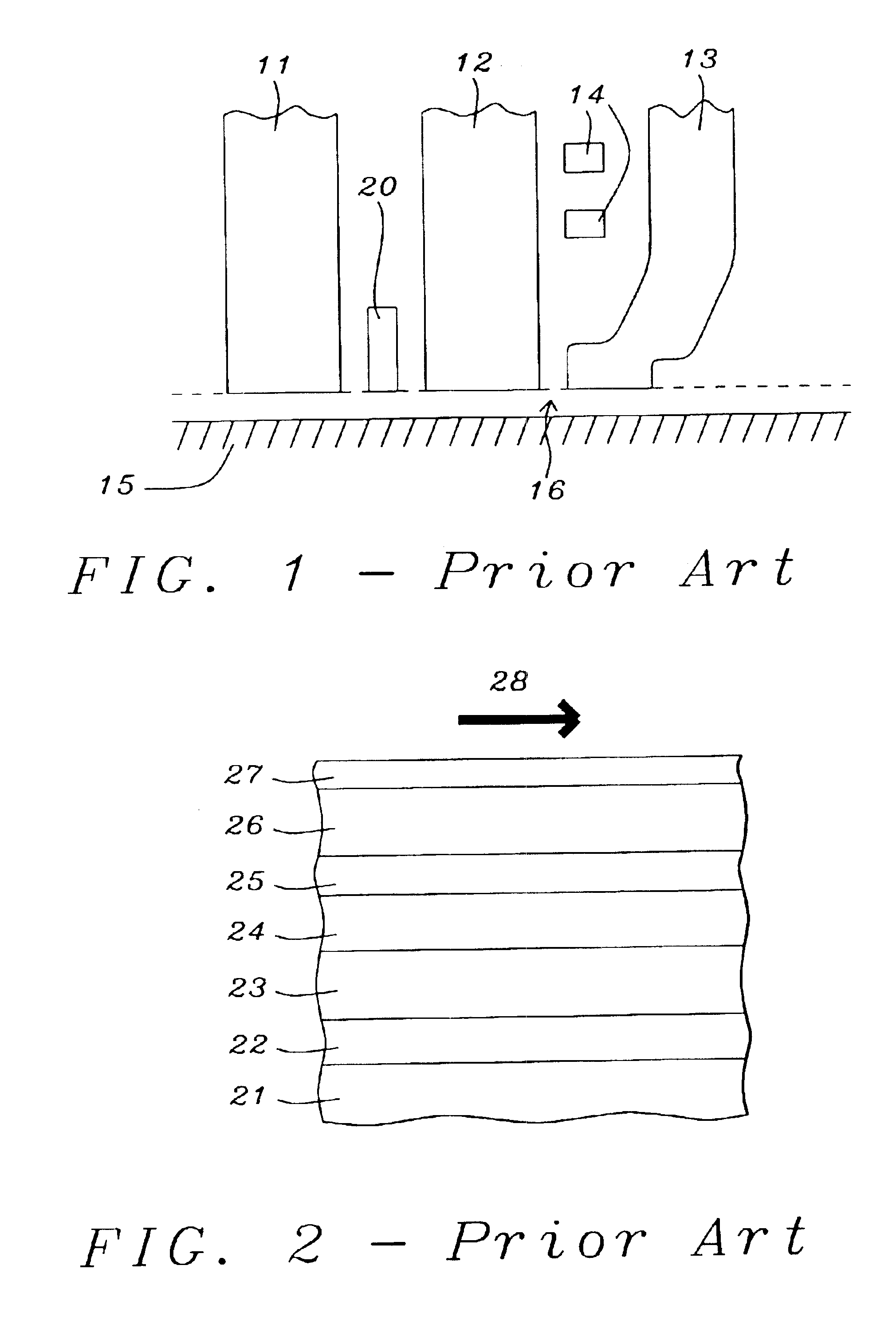
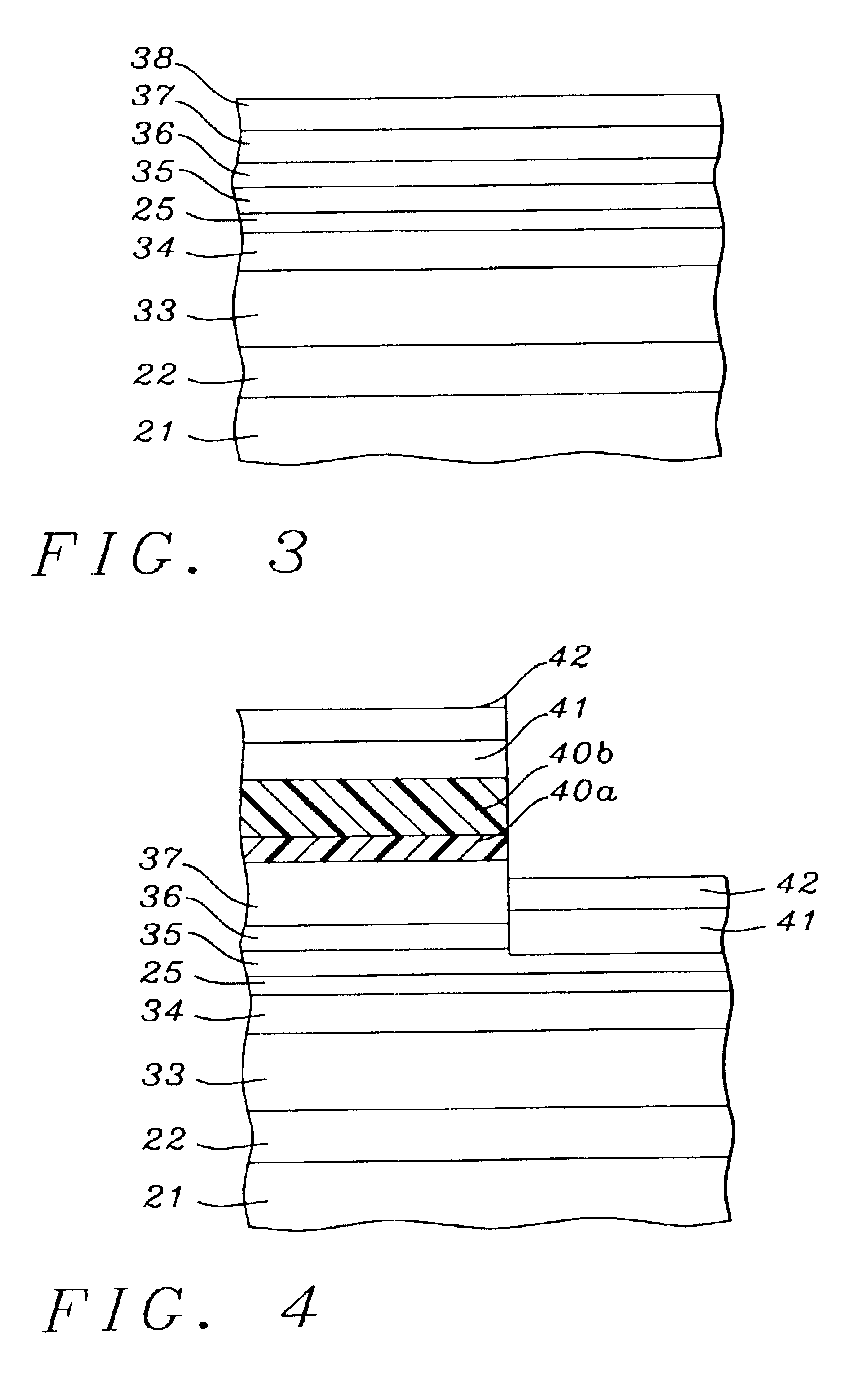
[0001]“This is a division of U.S. patent application Ser. No. 09 / 633,768, filing date Aug. 7, 2000, U.S. Pat. No. 6,517,896, Spin Filter Bottom Spin Valve Head With Continuous Exchange Bias, assigned to the same assignee as the present invention.”FIELD OF THE INVENTION[0002]The invention relates to the general field of GMR recording heads for magnetic disk systems with particular reference to design of the free layer.BACKGROUND OF THE INVENTION[0003]Read-write heads for magnetic disk systems have undergone substantial development during the last few years. In particular, older systems in which a single device was used for both reading and writing, have given way to configurations in which the two functions are performed by different structures. An example of such a read-write head is schematically illustrated in FIG. 1. The magnetic field that ‘writes’ a bit at the surface of recording medium 15 is generated by a flat coil, two of whose windings 14 can be seen in the figure. The mag...

Claims


Application Information

Patent Timeline
Patent Type & Authority Patents(United States)
IPC IPC(8): H01F41/30H01F10/00H01F10/32H01F41/14G11B5/39G11B5/31G01R33/09H01F10/16H01F10/30H01L43/08H01L43/12
CPCB82Y10/00B82Y25/00B82Y40/00G11B5/3903H01F41/325H01F10/3272H01F41/302H01F10/3295H01F10/324G11B5/3163Y10T29/49034Y10T29/49044
Inventor HORNG, CHENG T.CHEN, MAO-MINLI, MINTONG, RU-YING
Owner HEADWAY TECH INC
Why Eureka
Try Eureka