Method and apparatus in a fluidized bed heat exchanger

a fluidized bed and heat exchanger technology, applied in the direction of fluidized bed heat exchangers, steam generation using hot heat carriers, combustion processes, etc., can solve the problems of increasing the cost, increasing the complexity of the system, and affecting the efficiency of heat transfer, so as to reduce the amount of uncooled particles flowing through the first outlet and increase the amount of particles coming into communication with the heat transfer surface. , the effect of efficient and wide-ranging adjustment of heat transfer

Inactive Publication Date: 2005-11-08
FOSTER WHEELER ENERGIA OY
View PDF29 Cites 55 Cited by
  • Summary
  • Abstract
  • Description
  • Claims
  • Application Information

AI Technical Summary

Benefits of technology

[0013]It is a more specific object of the invention to provide an improved method and apparatus that allows for easy adjustment of the heat transfer efficiency of a fluidized bed heat exchanger over a wide efficiency range.
[0031]In a heat exchange chamber in accordance with the invention, an efficient and wide-ranging adjustment of heat transfer may be realized simply by adjusting the velocity of the fluidization gas, and if necessary, by further adjusting the discharge of solid particles through a second outlet. By intensifying the particle flow through the second outlet, the amount of uncooled particles flowing through the first outlet is decreased and the amount of particles coming into communication with the heat transfer surfaces is increased. Conversely, by decreasing the particle flow through the second outlet, the immediate discharge of hot particles from the heat exchanger through the overflow opening is increased.

Problems solved by technology

Reasons for such adjustments may be a changing demand for steam production, a deviation in the fuel quality or in the feed of the fuel, or some other abnormality in the system.
In the disclosed arrangement, however, an additional flow channel and an adjustment valve are required, which makes the system more complicated and increases the costs.
Further, when changing the height of the bed, part of the heat transfer surfaces may be exposed to considerable erosion.
However, the disclosed arrangement is complicated and—in terms of space consumption—disadvantageous.
At high speeds, no separate cooled layers are allowed to form in close proximity to the heat transfer surfaces, which could decrease the heat transfer, nor will the hot particle flows entering the heat exchanger be passed directly from the inlet of the heat exchange chamber to the outlet without mixing with the particles in the chamber.
The adjustment range of the heat transfer efficiency in this kind of a heat exchange chamber may, however, remain rather limited.
Further, due to the use of a separate transfer area, the space utilization is not optimal, since a considerable part of the heat exchange chamber is not in efficient use with respect to the heat transfer.

Method used


Image

  • Method and apparatus in a fluidized bed heat exchanger
  • Method and apparatus in a fluidized bed heat exchanger
  • Method and apparatus in a fluidized bed heat exchanger

Examples


Embodiment Construction

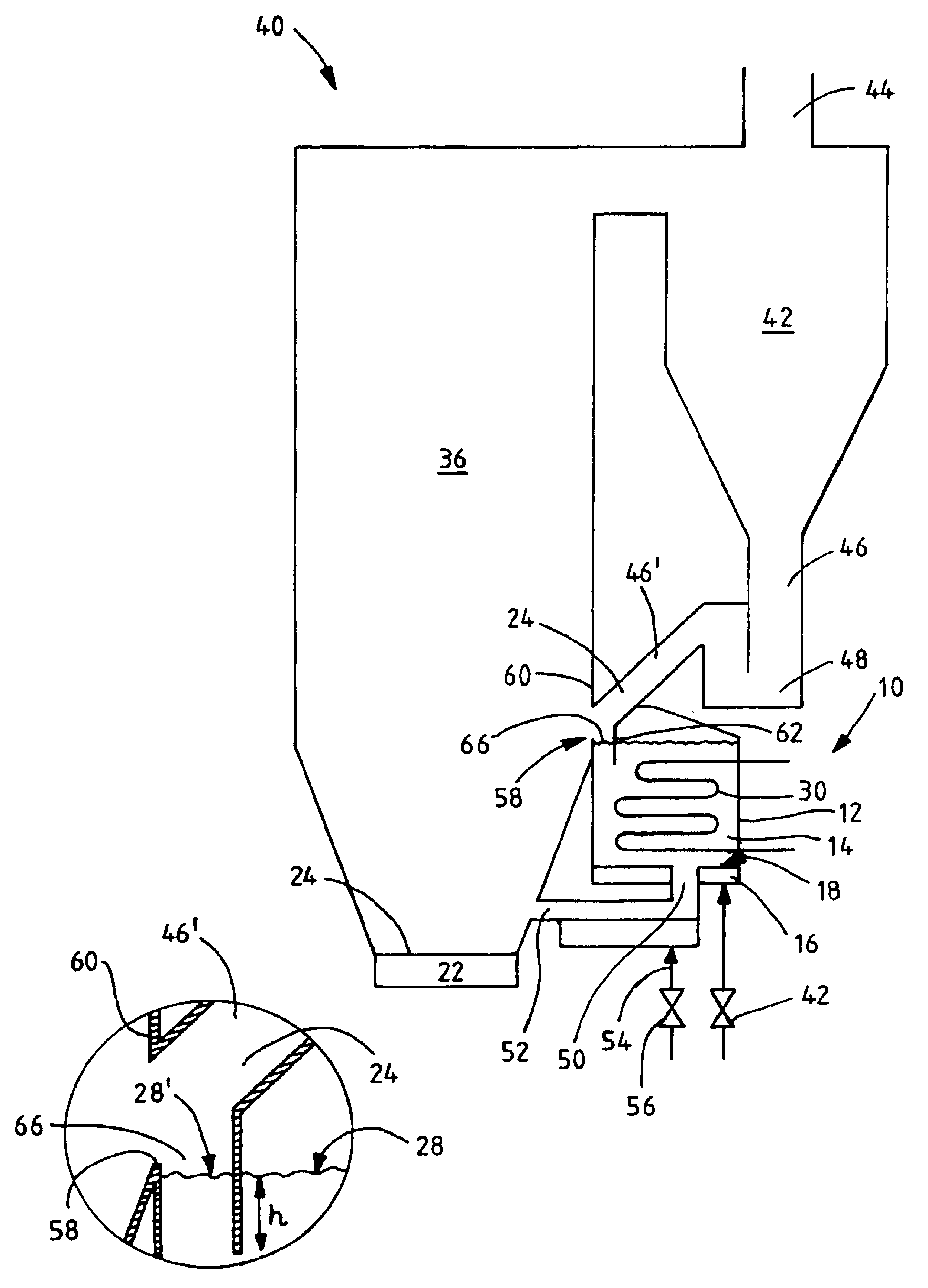
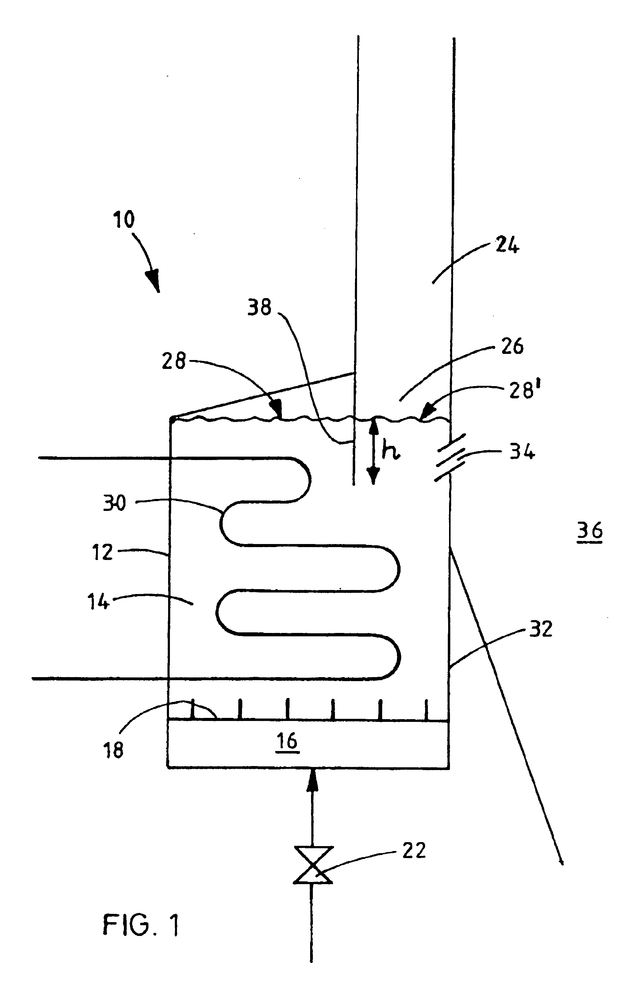
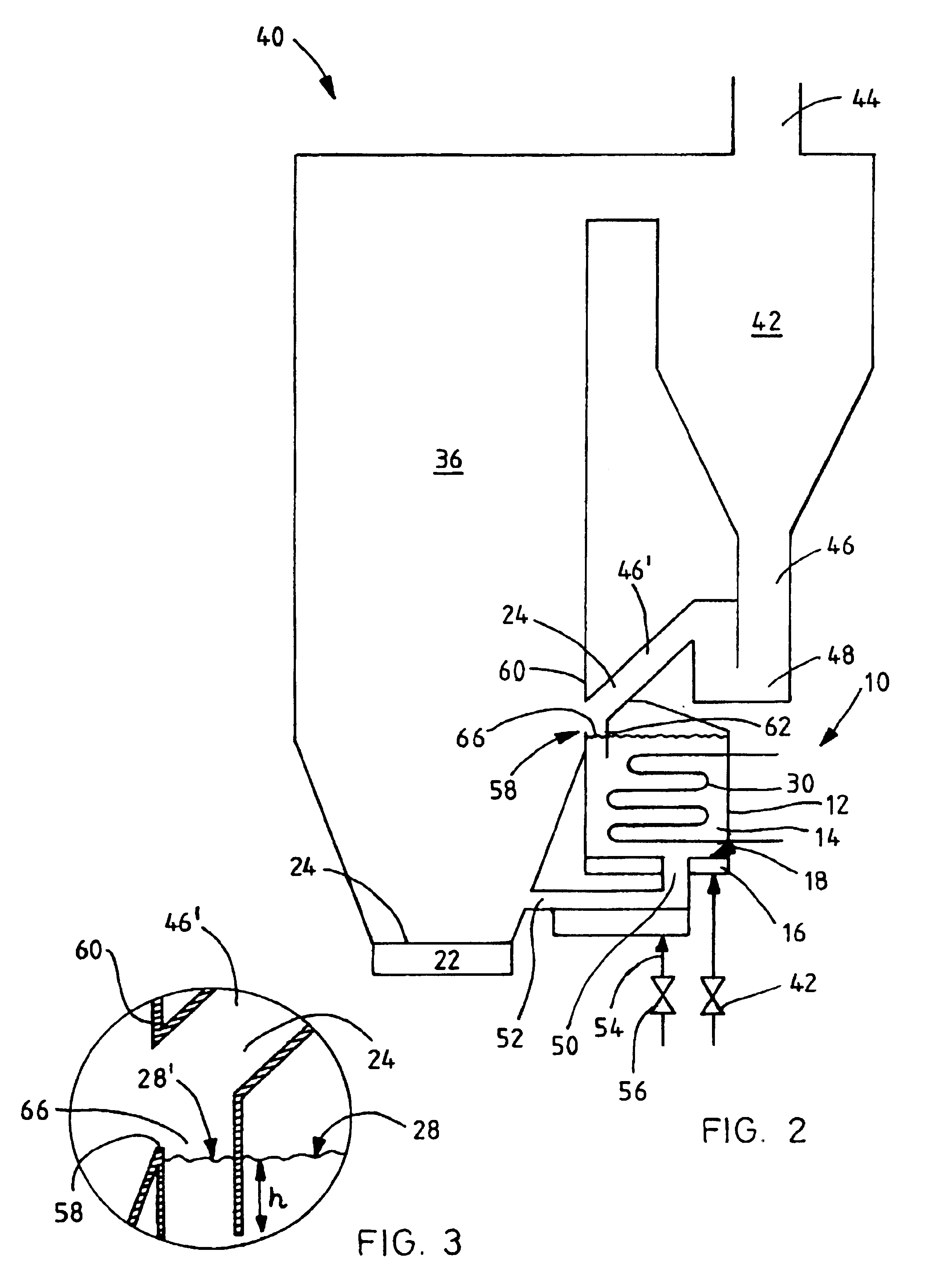
[0038]FIG. 1 schematically illustrates a simple heat exchanger 10, in the heat exchange chamber 12 of which a slow fluidized bed 14 comprising hot solid particles is maintained by feeding fluidization gas into it from a wind box 16 through a grid 18. Heat transfer surfaces 30 are arranged in the fluidized bed for the recovery of heat from the fluidized bed. The flow of the incoming fluidization gas from the wind box through the grid 18 may be adjusted by a valve 22, for example, to control the quantity of heat that is transferred to the heat transfer surfaces.

[0039]The top portion of the heat exchange chamber 12 above the fluidized bed 14 is provided with an inlet 24, from which hot solid particles flow through a guiding channel 26 onto the surface 28 of the fluidized bed 14.

[0040]Heat is recovered from the hot particles entering the fluidized bed in the heat exchange chamber 12 by transferring the heat energy of the hot solid particles to a medium, usually steam or water, contained...


PUM


Abstract

A method and an apparatus in a fluidized bed heat exchanger including a heat exchange chamber having a fluidized bed of solid particles, heat transfer surfaces, an inlet, and an outlet. Particles are fed through the inlet onto the upper surface of the bed of solid particles by a guiding channel. The guiding channel, which extends from above the upper surface of the bed of solid particles to the surface thereof, or to below the surface, passes the solid particles to the restricted area of the surface. The outlet is formed in the area of the guiding channel to remove particles from the area delimited by the guiding channel. Uncooled particles can thus be removed from the heat exchange chamber.

Description

BACKGROUND OF THE INVENTION[0001]The present invention relates to a method and an apparatus in a fluidized bed heat exchanger.[0002]In particular, the present invention relates to a method and an apparatus, by which heat transfer may be adjusted in a fluidized bed heat exchanger. The apparatus includes a heat exchange chamber having a bed of solid particles, means for feeding fluidization gas into the heat exchange chamber, heat transfer surfaces in contact with the bed of solid particles, an inlet arranged in the top portion of the heat exchange chamber above the upper surface of the bed of solid particles, and a first outlet for removing solid particles from the heat exchange chamber. The method, meanwhile, typically includes steps of feeding solid particles through the inlet to the upper surface of the bed of solid particles in the heat exchange chamber, fluidizing the bed of solid particles in the heat exchange chamber fluidization gas, transferring heat by the heat transfer sur...

Claims


Application Information

Patent Timeline
Patent Type & Authority Patents(United States)
IPC IPC(8): F23C10/00F22B31/00F23C10/10F28D13/00F22B1/02F23C10/02F23C10/28
CPCF22B31/0084F23C10/10F28D13/00
Inventor HYPPANEN, TIMO
Owner FOSTER WHEELER ENERGIA OY
Why Eureka
Try Eureka