
System and method for locating color and pattern match regions in a target image

a target image and color matching technology, applied in image enhancement, digitally marking record carriers, instruments, etc., can solve the problems of difficult characterizing colors difficult to achieve color matching with intensity/luminance independent features, and high computational intensity, etc., to achieve the effect of reducing the distance between sample points, reducing the number of points, and reducing the computational intensity

Inactive Publication Date: 2005-11-08
NATIONAL INSTRUMENTS
View PDF31 Cites 91 Cited by
  • Summary
  • Abstract
  • Description
  • Claims
  • Application Information

AI Technical Summary

Benefits of technology

[0034]The Low Discrepancy sequence may be designed to produce sample points which maximize the distance between sample points. Also, the Low Discrepancy sequence sampling may result in fewer points and / or a better characterization of the template image pattern information than a random sequence sampling or a uniform sampling. Examples of the Low Discrepancy sequence include Halton, Sobol, Faure, and Niederreiter sequences. The sampling or characterizations of the template image pattern and color information are preferably performed off-line prior to receipt of a target image. Thus, the analyses of the template image are preferably not constrained by real time requirements. After the candidate color match regions have been determined, pattern information of a region proximal to or surrounding each color match region may be compared to the pattern information of the template image, using the sample points determined in the pattern characterization method.
[0035]In another embodiment, the pattern characterization may involve sampling the template image, wherein the template image comprises a first plurality of pixels, and wherein the sampling produces a second lesser number of sample pixels. This sampling may use any of various sampling techniques, including a Low Discrepancy sequence as described above. A local stability analysis is then performed around at least a subset of the sample pixels to determine a lesser third number of sample pixels which have a desired degree of stability. The local stability analysis operates to ensure stability of each of the subset of sample pixels to spatial perturbations around the sample pixel. For each pixel, the local stability analysis preferably comprises finding a neighborhood around the sample pixel where the value, e.g., the grayscale value, of the sample pixel correlates highly with the template image pixel values in the neighborhood. The local stability analysis is preferably performed for all of the sample pixels. The third plurality of sample pixels may then be used in the pattern matching.
[0036]In one embodiment, the local stability analysis determines a plurality of sets of sample pixels with differing stability neighborhood sizes, and the pattern matching performed for each region surrounding a candidate color match region comprises performing a plurality of iterations of pattern matching using different sets of sample pixels. The iterations are preferably performed in a coarse to fine manner, e.g., using sets of sample pixels with successively smaller stability neighborhood sizes. This plurality of iterations of pattern matching may also use different step sizes for each of the different sets of sample pixels, wherein the step size preferably corresponds with the stability neighborhood size. Thus the plurality of iterations of pattern matching in the coarse to fine manner preferably uses sets of sample pixels with successively smaller stability neighborhood sizes and / or successively smaller step sizes. For example, a first iteration of pattern matching may determine one or more candidate pattern match regions in the region which possibly match the pattern information of the template image, and one or more second iterations of pattern matching may then be performed at the determined one or more candidate pattern match regions in the region, and so on.
[0037]The techniques described herein may also be used to perform pattern matching to locate one or more instances of a rotated or scaled color template image in a color target image. The pattern characterization of the template image may comprise first sampling the template image along one or more rotationally invariant paths, preferably circular perimeters, to produce one or more sets of sample pixels. The pattern matching performed may then use a cyclic correlation between each of the one or more sets of sample pixels and the target image to determine zero or more regions of the template image in each region surrounding a color match candidate region. This pattern matching detects rotated versions of the template image in the target image.
[0038]In one embodiment, a local stability analysis around at least a subset of the sample pixels may be performed. The pattern matching may then use one or more sets of sample pixels along one or more circular perimeters based on the local stability analysis. The local stability analysis preferably determines a plurality of sets of sample pixels with differing stability neighborhood sizes. In this case, the pattern matching comprises performing a plurality of iterations of pattern matching using different sets of sample pixels, preferably in a coarse to fine manner, e.g., using sets of sample pixels from circular paths with successively smaller stability neighborhood sizes. The pattern matching may also use different step sizes for each of the different sets of sample pixels. As discussed above, a first iteration of pattern matching within each region may determine one or more candidate pattern match locations and corresponding rotation values in the target image, and one or more second iterations of pattern matching may be performed at the determined one or more candidate pattern match locations in the region using the respective rotation values, and so on. A final pattern matching may utilize substantially all of the template image pixels at the respective candidate locations and using the determined rotation values.

Problems solved by technology

This approach is thus very computationally intensive.
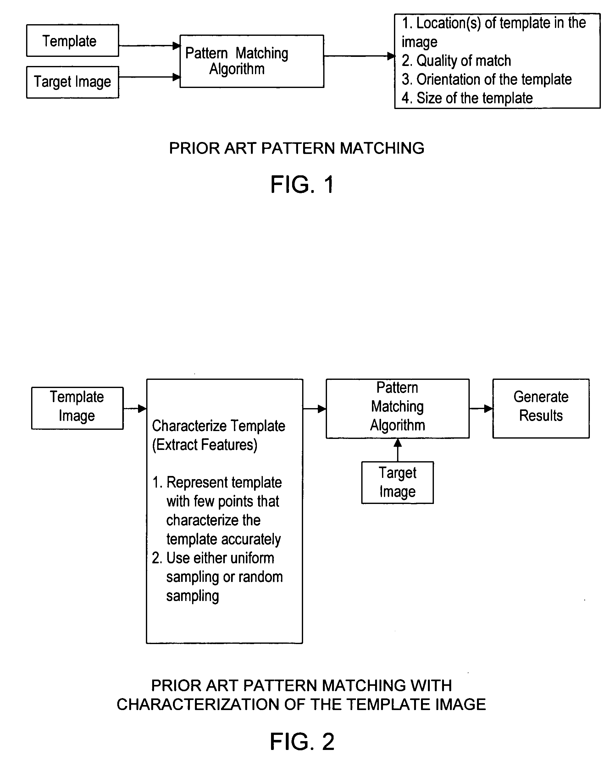
However, each of the above prior art techniques operates to select a subset of the pixels in the template image which do not necessarily represent or characterize the template image well.
In other words, homogeneous sampling or random sampling of the template image often does not produce an optimum subset of samples or pixels which best represent the pattern information of the template image.
Because the red, green, and blue color components in RGB color space are highly correlated, it is difficult to characterize colors with intensity / luminance independent features.
In RGB mode it is not possible to separate color from intensity.
However, it is difficult to distinguish multiple color objects by the thresholding technique, especially when the saturation has to be taken into account.
Moreover, the black and white colors are the background colors in many machine vision applications and chromaticity (i.e. hue and saturation) can not be used to represent them.
The computation cost of pixel by pixel comparison is very expensive and is difficult to accomplish in real time.
This process cannot be used to measure the colors quantitatively in an image or to measure the quantitative color similarities between two objects in an image or in two separated images.
Although a special hardware addressing approach can improve the processing speed, the cost of computation is still very high for sorting objects with complex colors.
Similar to the Jones' patent as described above, the cost of computation of the distance is very high.
A further drawback of this approach is that it is impossible to have scale and rotation-invariant color matching based on the ‘distance’ measure.

Method used


Image

  • System and method for locating color and pattern match regions in a target image
  • System and method for locating color and pattern match regions in a target image
  • System and method for locating color and pattern match regions in a target image

Examples


Embodiment Construction

Incorporation by Reference

[0065]The following patent applications are hereby incorporated by reference in their entirety as though fully and completely set forth herein:

[0066]U.S. patent application Ser. No. 09 / 375,453 titled “System and Method for Color Characterization with Applications in Color Measurement and Color Matching” filed on Aug. 17, 1999, whose inventors are Siming Lin and Dinesh Nair;

[0067]U.S. patent application Ser. No. 09 / 227,506 titled “Pattern Matching System and Method Which Performs Local Stability Analysis for Improved Efficiency” filed on Jan. 6, 1999, whose inventors are Dinesh Nair, Lothar Wenzel, Nicolas Vazquez, and Samson DeKey;

[0068]U.S. patent application Ser. No. 09 / 639,420 titled “System and Method for Locating Color Match Regions in a Target Image,” filed on Aug. 14, 2000.

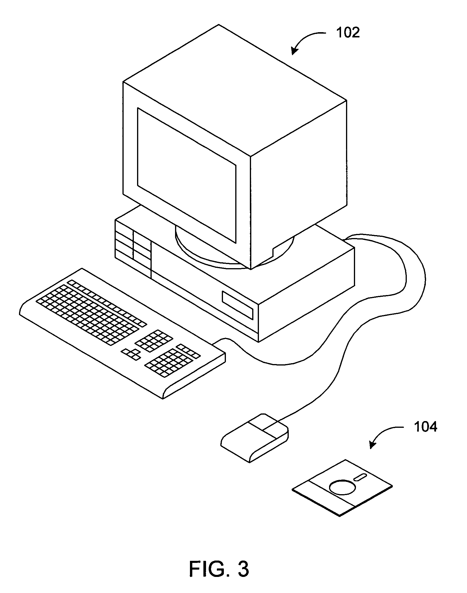
FIG. 3—Computer System

[0069]FIG. 3 illustrates a computer system 102 which may perform color and pattern match location according to the present invention. The computer system 102 ...


PUM


Abstract

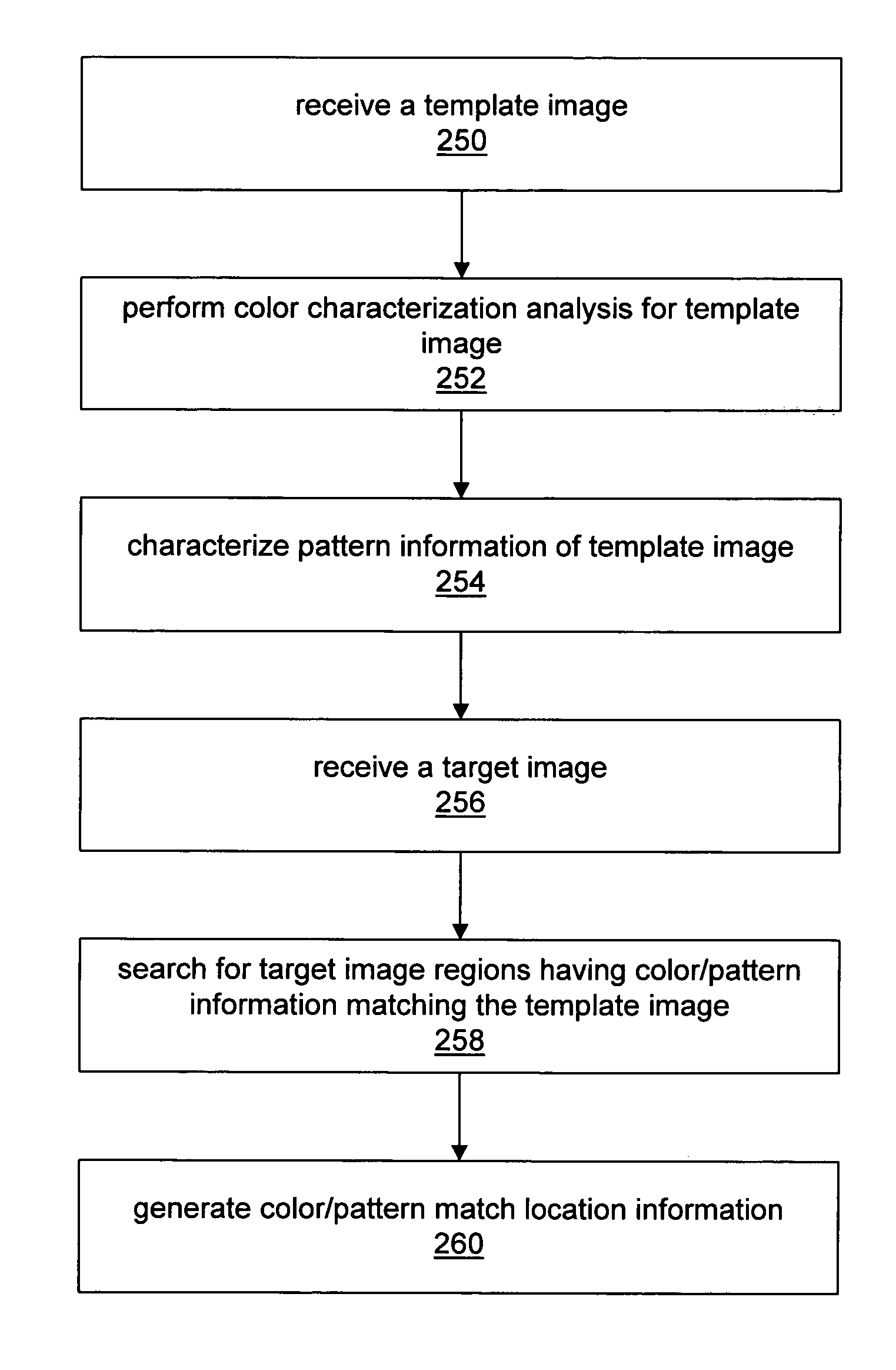
A system and method for locating regions in a target image that match a template image with respect to color and pattern information. The method may comprise performing a first-pass search using color information obtained in a color characterization analysis of the template image in order to find a plurality of color match candidate locations. For each color match candidate location, a region proximal to the location may then be searched in detail, based on pattern information obtained in a pattern analysis of the template image.

Description

FIELD OF THE INVENTION[0001]The present invention relates to a system and method for locating regions of a target image that match a template image with respect to color and pattern information, wherein the invention includes efficient methods for characterizing the template image, improved methods for performing the color and pattern matching, and improved methods for locating rotated and / or scaled matches.DESCRIPTION OF THE RELATED ART[0002]In many applications it is necessary or desired to find one or more matches of a template image in a larger target image. Such applications include machine vision applications including process monitoring, feedback control, and laboratory automation; image and video compression; and jitter compensation in video cameras, among others. Various characteristics may be used in classifying a location in the target image as a match, including color and / or pattern information.[0003]Prior art pattern recognition systems have typically used a template ma...

Claims


Application Information

Patent Timeline
Patent Type & Authority Patents(United States)
IPC IPC(8): G06K1/00G06F15/00G06V10/56
CPCG06K9/4652G06K9/6203G06T7/0006G06T7/408G06T2207/30141G06T7/90G06V10/56G06V10/7515
Inventor NAIR, DINESHLIN, SIMINGSCHMIDT, DARRENVAZQUEZ, NICOLAS
Owner NATIONAL INSTRUMENTS
Learn More