High-sensitivity wireless receiving device and high-frequency unit used therefor

a wireless receiving device and high-frequency unit technology, applied in the field of high-sensitivity radio receiver systems, can solve the problems of degradation of the noise figure the inability to receive, etc., and achieve the effect of low nois

Inactive Publication Date: 2005-11-08
NTT DOCOMO INC
View PDF8 Cites 20 Cited by
  • Summary
  • Abstract
  • Description
  • Claims
  • Application Information

AI Technical Summary

Benefits of technology

[0007]It is an object of the present invention to provide a high sensitive radio receiver system which has an excellent noise figure and which is operable even when one of a plurality of cooling units fails. It is another object of the present invention to provide a high frequency unit for use in the high sensitive radio receiver system which is capable of delivering a received h.f. signal even if a fault occurs with the cooling of a superconducting bandpass filter.

Problems solved by technology

If the cooling function applied to these bandpass filters ceases to operate and allows the temperature to rise, thermal noises generated within the bandpass filters increase, and there results a degradation in the noise figure which has been kept improved by the cooling function, leading to a degradation in the received signal or a failure of reception.
In particular, when the bandpass filters are composed of superconducting bandpass filters, a fault in the cooling unit results in not only a degradation of the noise figure, but also a problem that the reception is disabled in all the sectors.
This is because the superconducting bandpass filters cannot be maintained in the superconducting state after exceeding the critical temperature.
This problem is quite remarkable when the bandpass filters connected to the plural antennae in each sector are cooled in a single vacuum chamber (heat shielding box) to reduce the total number of the cooling units corresponding to the sectors for economic purpose.
However, a failure in one of these cooling units disables the reception of the corresponding sector, even though the cooling unit is provided separately for each sector.
However, there remains a problem that the reception by the high sensitive radio receiver system may be disabled by a rapid degradation in the performance of superconducting bandpass filters as a result of an aging effect of the cooling unit or a rise in the cooling temperature upon occurrence of a failure.
This is because even an extremely high-reliable cooling unit cannot be free from a failure.

Method used


Image

  • High-sensitivity wireless receiving device and high-frequency unit used therefor
  • High-sensitivity wireless receiving device and high-frequency unit used therefor
  • High-sensitivity wireless receiving device and high-frequency unit used therefor

Examples


first embodiment

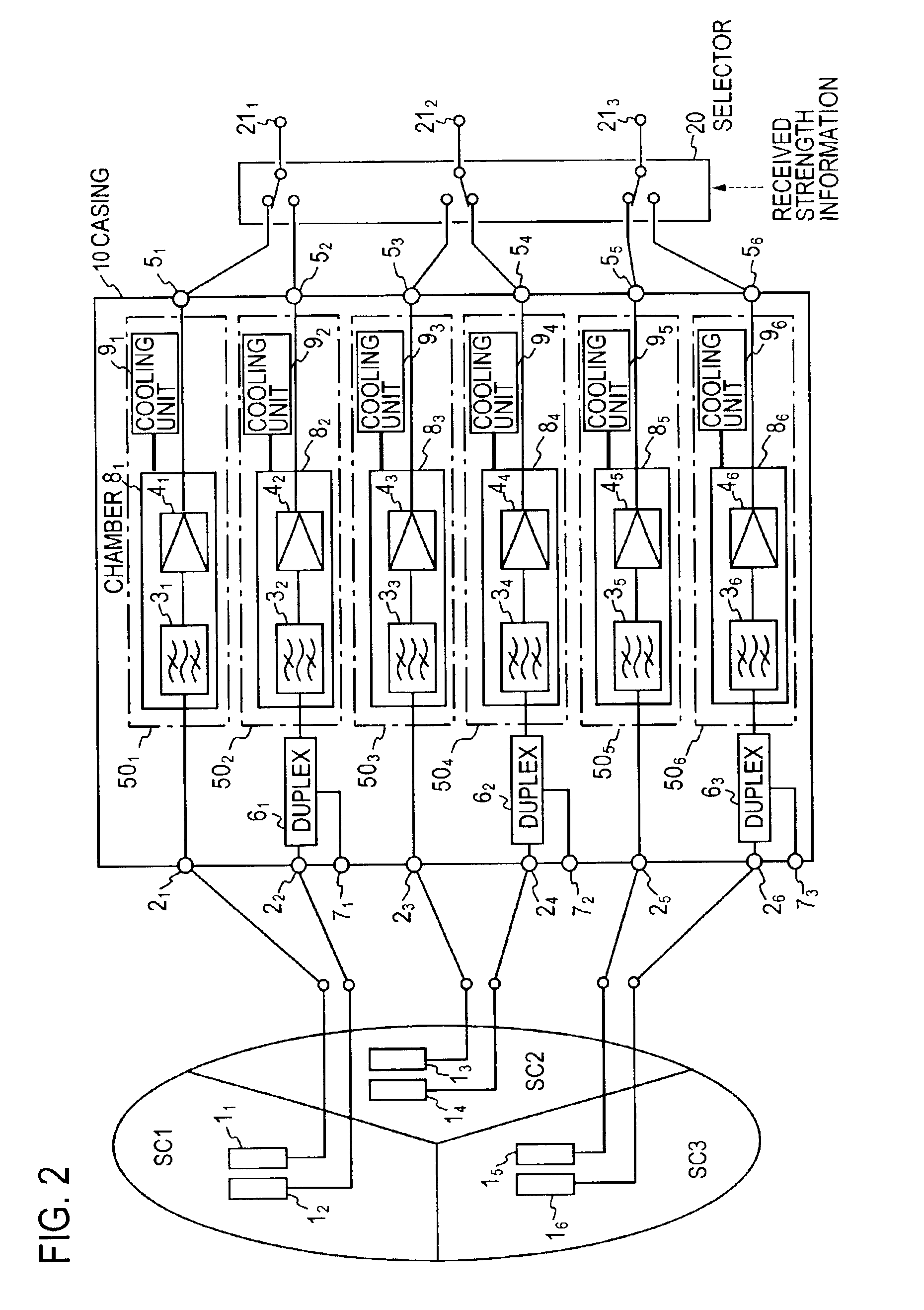
[0036]An embodiment of the invention for a conventional high sensitive radio receiver system is shown in FIG. 2 where three sectors are used.

[0037]In a mobile communication in which the high sensitive radio receiver system is used, a signal is received by applying the space diversity technique using two antennae per sector. In the example shown in FIG. 2, one of the two antennae is shared for transmission and reception. The high sensitive radio receiver system comprises an antenna terminal 21 to which a received signal from an antenna 11 of sector SC1 is input, a bandpass filter 31 which selects a signal in a desired band from the received h.f. signal input from an antenna terminal 21, a low noise amplifier 41 for amplifying an output from a bandpass filter 31 with a low noise response, and an output terminal 51 which delivers the received h.f. signal that is amplified by the low noise amplifier 41. The high sensitive radio receiver system is often installed outdoors or in the vicin...

second embodiment

[0048]FIG. 4 shows a second embodiment of the high sensitive radio receiver system according to the present invention. In this embodiment, two vacuum chambers 81, 82 are disposed in the casing 10. The vacuum chamber 81 contains superconducting bandpass filters 31, 32, 33 and low noise amplifiers 41, 42, 43 which are connected to the filter outputs. The vacuum chamber 82 contains superconducting bandpass filters 34, 35, 36 and low noise amplifiers 44, 45, 46 which are connected to the filter outputs. Outputs from the low noise amplifiers 41 to 43 and 44 to 46 are connected through output terminals 51 to 53 and 54 to 56 selectively to the three diversity amplifiers which are located outside the casing 10 though not shown in FIG. 4. The interior of vacuum chambers 81 and 82 is cooled by cooling unit 91 and 92, respectively. In this embodiment, three sets of the bandpass filters 31 to 33 and the low noise amplifiers 41 to 43 which are connected in series, the vacuum chamber 81 and the c...

third embodiment

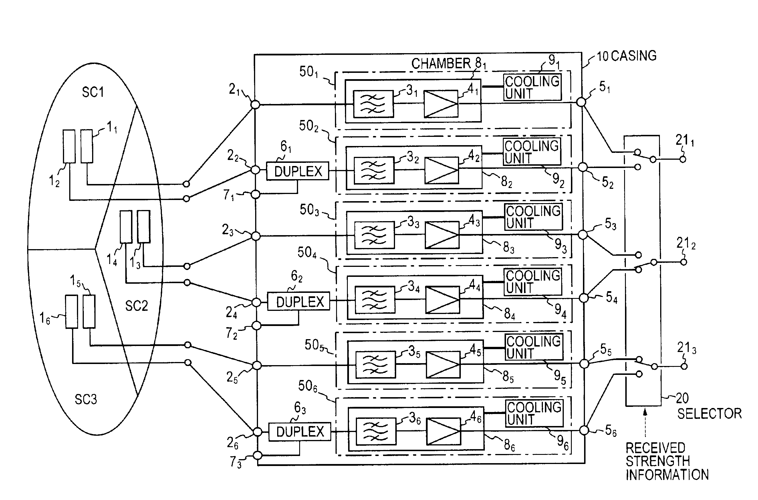
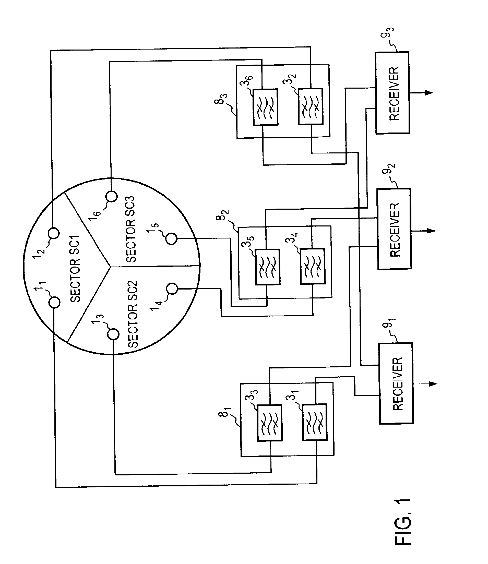
[0053]FIG. 5 shows a third embodiment of the high sensitive radio receiver system according to the present invention. In this embodiment, three vacuum chambers 81, 82, 83 and associated cooling units 91, 92, 93 are disposed in a casing 10, respectively. Two antennae of each sector are connected to different bandpass filters which are contained in two of the three vacuum chambers 81, 82, 83, in a similar manner as in the prior art shown in FIG. 1. The vacuum chamber 81 contains bandpass filters 31, 32 and low noise amplifiers 41, 42 connected thereto; the vacuum chamber 82 contains bandpass filters 33, 34 and low noise amplifiers 43, 44 connected thereto; and the vacuum chamber 8 contains bandpass filters 35, 36 and their connected low noise amplifiers 45, 46 connected thereto.

[0054]In this embodiment, two sets of bandpass filters 31, 32 and the low noise amplifiers 41, 42 which are connected in series, the vacuum chamber 81 and the cooling unit 91 form two high frequency receiver un...


PUM


Abstract

In a high sensitive radio receiver system for a diversity reception from two antennae per each of three sectors (SC1, SC3, SC3), a series connection of a bandpass filter (31 to 36) and a low noise amplifier (41 to 46) is contained in each of a plurality of vacuum chambers (81 to 86), the interior of which is cooled by a distinct, separate cooling unit (91 to 96). The two antennae per sector are connected to bandpass filters contained in different vacuum chambers.

Description

TECHNICAL FIELD[0001]The present invention relates to a high sensitive radio receiver system including bandpass filters which are cooled for reception of a desired high frequency signal as may be used in a base station radio equipment for mobile communication system, for example, and a high frequency receiver unit for use in such a receiver system.PRIOR ART[0002]For a base station of a mobile communication system which includes a plurality of sectors, space diversity reception technique is employed for each sector in order to attain high sensitive reception of the signal transmitted from a mobile station. In this instance, the transmitted signal from the mobile station is received by the plurality of antennae, and in order to achieve high C / N(carrier to noise ratio) characteristics, the received high frequency (hereafter h.f.) signals from the antennae in each sector are processed by the bandpass filters of predetermined characteristics which are cooled with extremely low temperatur...

Claims


Application Information

Patent Timeline
Patent Type & Authority Patents(United States)
IPC IPC(8): H04B1/02H04B7/04H04B1/036H04B1/18
CPCH04B1/036H04B1/18H04B7/0491H04B1/74
Inventor NARAHASHI, SHOICHIKAWAI, KUNIHIROSATOH, KEINOJIMA, TOSHIO
Owner NTT DOCOMO INC
Why Eureka
Try Eureka