
Intermittent application of syngas to NOx trap and/or diesel engine

a technology of nox trap and diesel engine, which is applied in the direction of machines/engines, mechanical equipment, and non-fuel substance addition to fuel, etc., can solve the problems of increasing the cost of the system, cpo catalyst melt or damage, and great challenge in starting up and shutting down a cpo, so as to improve the overall efficiency and clean operation of internal combustion engines. , the effect of improving the utilization rate of a cpo

Inactive Publication Date: 2005-11-15
SHELL OIL CO
View PDF13 Cites 24 Cited by
  • Summary
  • Abstract
  • Description
  • Claims
  • Application Information

AI Technical Summary

Benefits of technology

The invention is about improving the use of a chemical called CPO in vehicles to reduce emissions. It suggests ways to restart the CPO quickly and efficiently, and to produce syngas for regenerating NOx traps. The invention also proposes a method to reduce fuel and exhaust during periods when syngas is not needed, by diverting it into the engine's fuel system or reducing the amount of fuel and exhaust applied to the CPO. These improvements can lead to better engine performance and cleaner emissions.

Problems solved by technology

To do this, the CPO must remain heated; otherwise, there would be a great challenge for starting up and shutting down a CPO frequently.
Startup and shutdown of the CPO requires significant, complex controls, thus increasing the cost of the system.
Furthermore, on start-up, the catalyst within the CPO potentially goes through a dangerous oxygen / carbon ratio locally, which could potentially melt or damage the CPO catalyst.
Although a CPO could simply be left in the operating condition, and the syngas discarded, this would result in a significant fuel penalty, causing an impermissibly low overall efficiency of the engine system.

Method used


Image

  • Intermittent application of syngas to NOx trap and/or diesel engine
  • Intermittent application of syngas to NOx trap and/or diesel engine
  • Intermittent application of syngas to NOx trap and/or diesel engine

Examples


Embodiment Construction

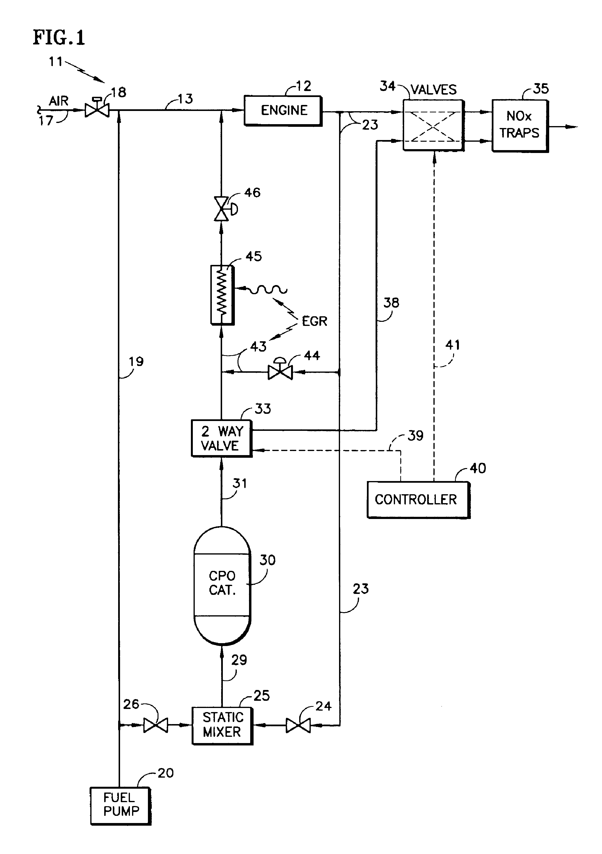
[0013]Referring to FIG. 1, an engine system 11 includes an internal combustion engine 12 which receives a mixture of fuel and air in a line 13. Air on a line 17 typically is provided by a turbo charger, the pressure of the air being suitably regulated by a valve 18. Fuel is provided on a line 19 from a fuel pump 20. The exhaust of the engine on a line 23 is provided through a fixed orifice 24 to a static mixer 25 along with fuel from the line 19, which is passed through a fixed orifice 26. The output of the static mixer on a line 29 is applied to a principal CPO 30, which generates a gaseous mixture of hydrogen, carbon monoxide and other gases, all as is conventional and not relevant to the invention. The output of the CPO on a line 31 is applied to a two-way valve 33, although it could be a valve having more selections as is described hereinafter.

[0014]The exhaust on line 23 is also provided to an apparatus, utilizing syngas, such as a set of valves 34 feeding a pair of NOx traps 3...


PUM

PropertyMeasurementUnit
timeaaaaaaaaaa
timeaaaaaaaaaa
adsorptionaaaaaaaaaa

Abstract

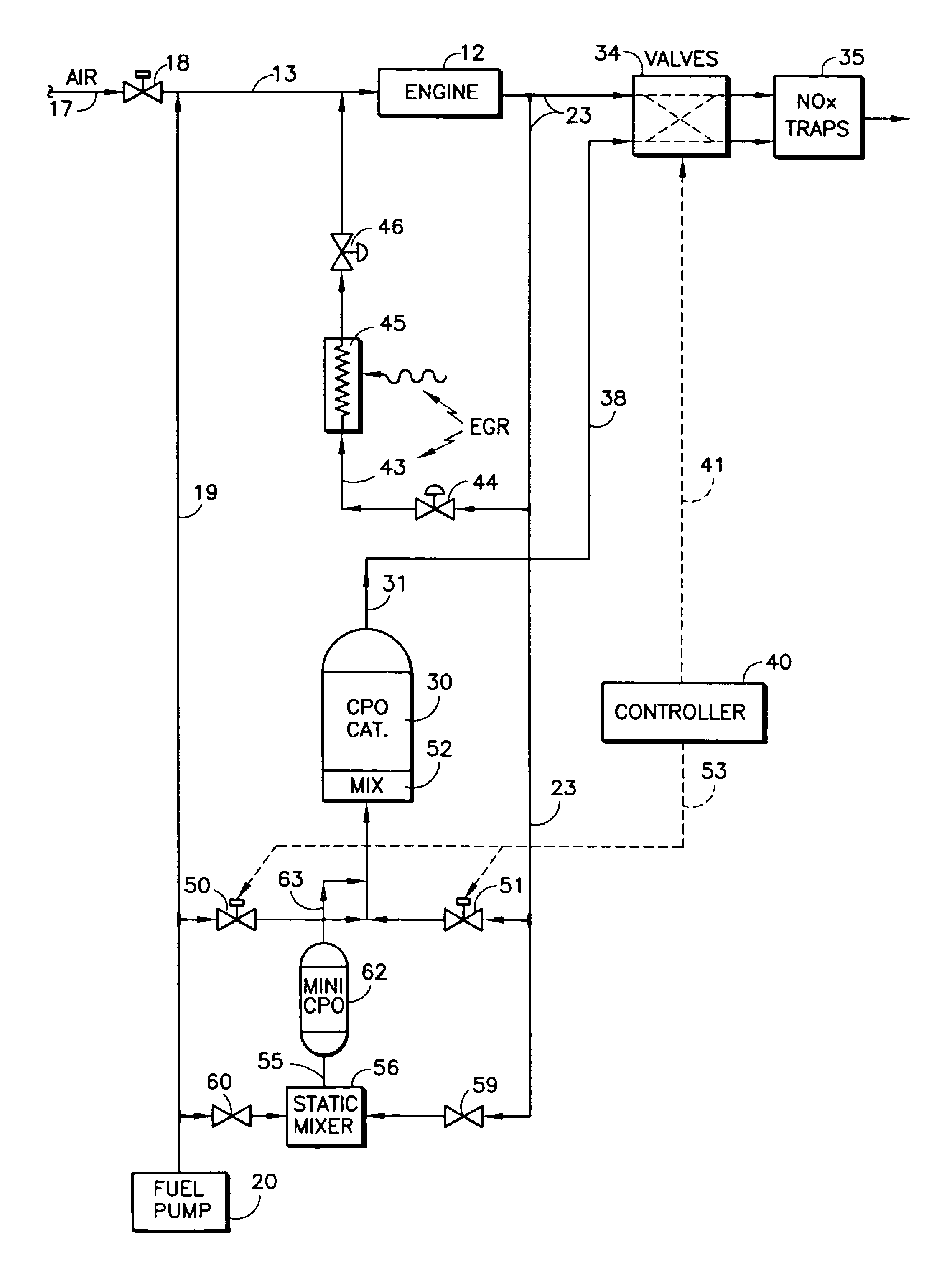
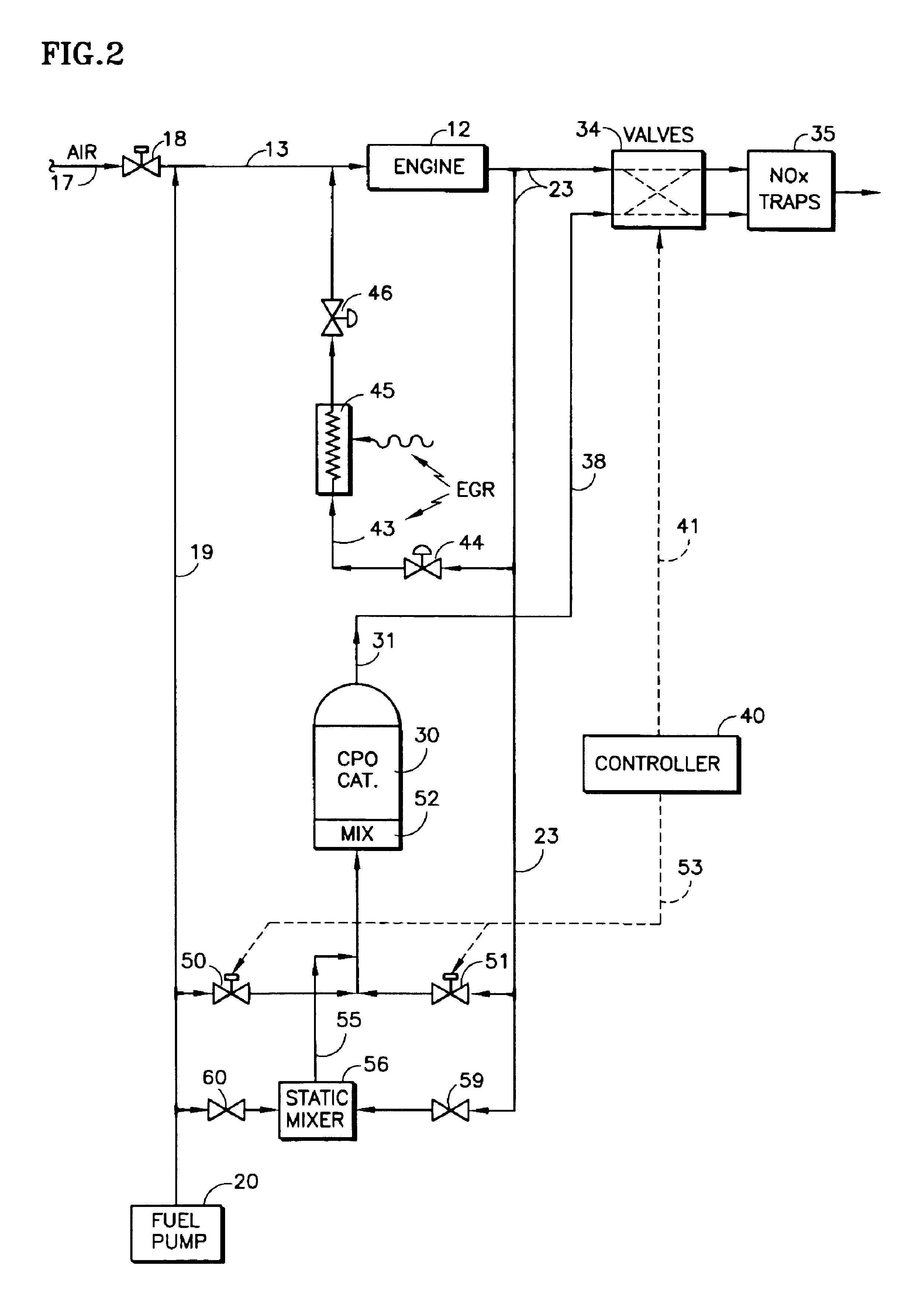
A catalytic partial oxidizer (30) provides syngas (hydrogen and carbon monoxide) to an apparatus intermittently using syngas such as valves (34) feeding NOx traps (35), for brief periods of time. During turndown times when syngas is not being used, either the output of the CPO is diverted (33) to the inlet (13) of an engine (12) through the engine gas recycle (EGR) system (43-46), or the amount of fuel (19) and exhaust (23) applied to the CPO is reduced (24, 26; 59, 60) so that the CPO merely stays warm and in a reduced state, thereby being ready to restart immediately. A mini-CPO (62) may provide syngas and heat to the major CPO (30) during the turndown time when syngas is not being used by the NOx traps.

Description

TECHNICAL FIELD[0001]This invention relates to accommodating the intermittent application of synthetically generated mix of hydrogen, carbon monoxide and other gases (syngas, hereinafter) in vehicles having internal combustion engines, for any intermittent utilization, such as regeneration of the adsorption material in NOx traps, either (a) by diverting the syngas from the consuming apparatus (such as NOx traps) to the inlet of the engine, (b) by reducing the intake of the syngas generator so that it merely remains warm, or (c) using a continuously running mini-CPO to feed the main CPO sufficiently to keep it warm, so it can be restarted immediately.BACKGROUND ART[0002]On vehicles having internal combustion engines, in order to reduce oxides of nitrogen (NOx) in the exhaust, it is known to produce a gaseous mixture of hydrogen, carbon monoxide (referred to hereinafter as syngas), which can be used in a variety of ways, such as in the regeneration of adsorption material in NOx traps....

Claims


Application Information

Patent Timeline
Patent Type & Authority Patents(United States)
IPC IPC(8): F01N3/20F01N3/08F01N9/00C01B3/38F02M25/07
CPCC01B3/386F01N3/0842F01N3/0871F01N3/206F01N9/00C01B2203/0261C01B2203/1282C01B2203/1685F01N2240/30F01N2390/02F01N2610/04F01N2610/05F01N2610/146F02M25/0727F02M25/0742Y02T10/47Y02T10/24F02M26/23F02M26/36Y02T10/12Y02T10/40F01N3/00
Inventor LIU, KEWNUCK, WAYNE G.LEENHOUTS, WILLEM P.
Owner SHELL OIL CO
Learn More