Optimized heating value in natural gas liquids recovery scheme

a recovery scheme and heating value technology, applied in the field of natural gas liquid recovery, can solve the problems of reducing the separation efficiency of the fractionation column, unable to account for the process flexibility, and rejecting gas, so as to reduce the heating value of the residue gas

Active Publication Date: 2005-11-15
ABB LUMMUS GLOBAL INC
View PDF17 Cites 53 Cited by
  • Summary
  • Abstract
  • Description
  • Claims
  • Application Information

AI Technical Summary

Benefits of technology

[0011]The present invention advantageously provides a process and apparatus to control and decrease heating value of residue gas that is produced from natural gas liquids recovery processes. The process and apparatus additionally provides an increase in the amount of natural gas liquids that are recovered simultaneously with the reduction of the residue gas heating value.
[0015]As an alternate embodiment, the feed stream can be split prior to being heated. A first portion of the feed stream is sent directly to the tower as a first tower feed stream, while a secondary portion is heated and then sent to the tower as a second feed stream. It is preferable for the first tower feed stream to be fed to the tower at a higher location than the second tower feed stream. This alternate embodiment simplifies the heating requirements since only one heat exchanger with one heating path is required, but more than one can be used.
[0016]The result of both embodiments of the natural gas liquids recovery process is a decrease in the heating value of the residue gas LNG stream. The reduced heating value of the residue gas stream keeps the gas within the pipeline specifications. The recovery of natural gas liquids, such as C2+ compounds, provides a valuable source of revenue. Both embodiments are believed to be equally effective, with the second embodiment requiring less capital costs since less process equipment is needed.

Problems solved by technology

Difficulties encountered with the process of Markbreiter include a lack of flexibility in the process to account for varying feed compositions.
The Markbreiter process can result in an overhead stream, which is delivered as a vapor stream, with an unacceptably high amount of C2, which can result in rejection of the gas.
The cold reflux stream is pressurized so that its bubble point temperature is about −170° F., as opposed to conventional LNG processes having a bubble point about −260° F., which reduces separation efficiency within the fractionation column.

Method used


Image

  • Optimized heating value in natural gas liquids recovery scheme
  • Optimized heating value in natural gas liquids recovery scheme

Examples


Embodiment Construction

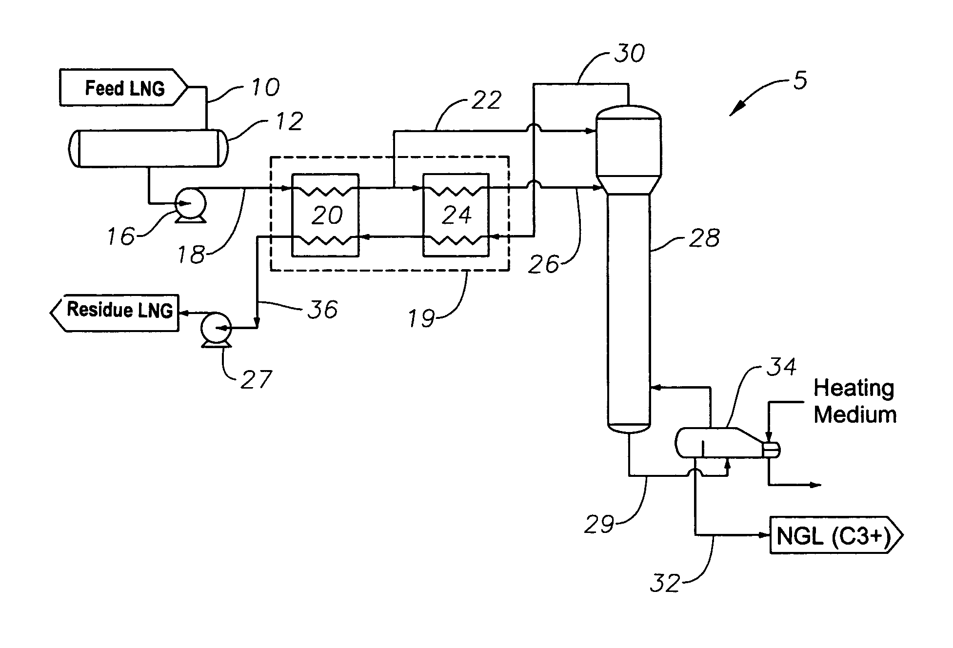
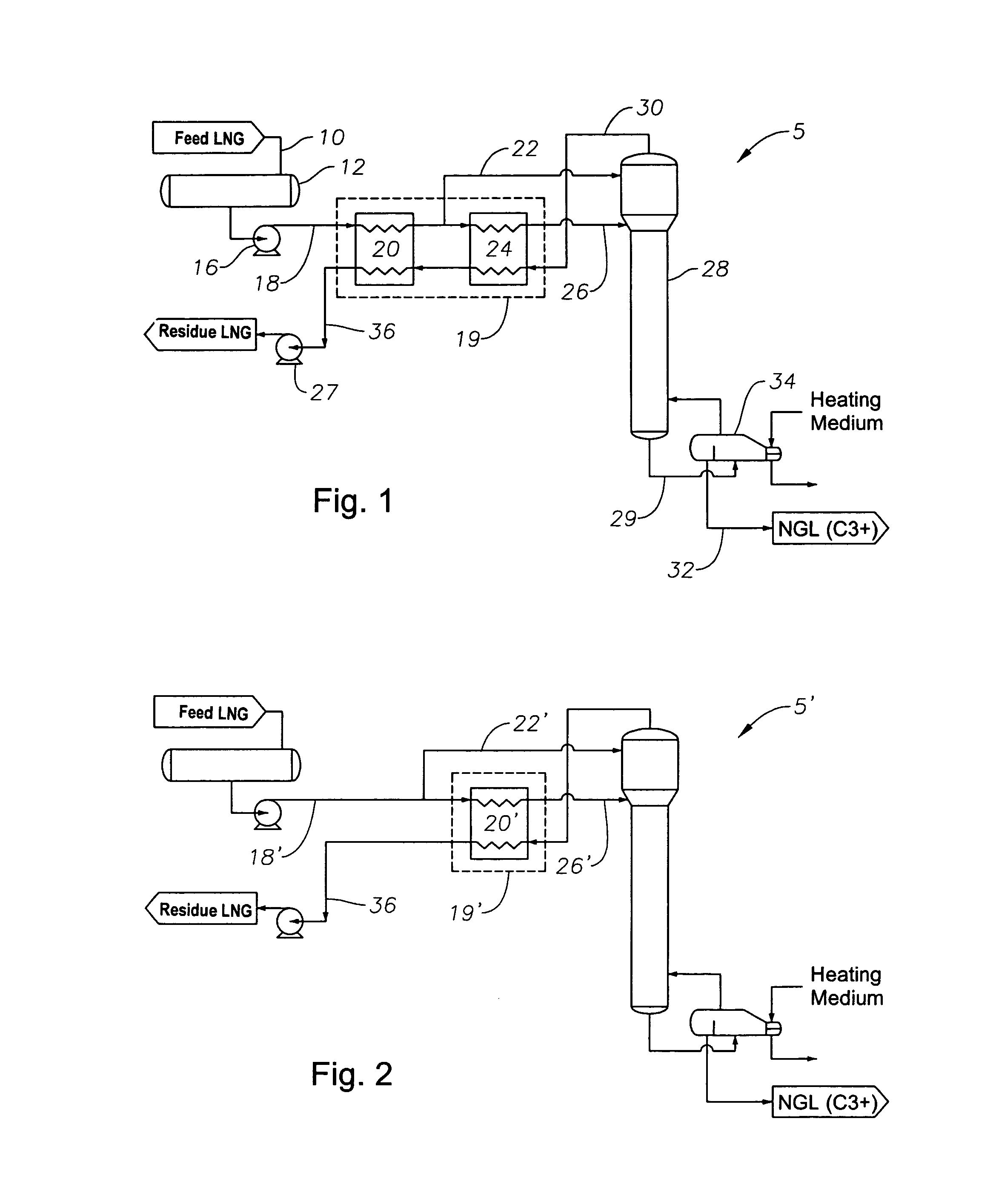
[0021]For simplification of the drawings, figure numbers are the same in FIG. 1 and FIG. 2 for various streams and equipment when the functions are the same, with respect to the streams or equipment, in each of the figures. Like numbers refer to like elements throughout, and prime, double prime, and triple prime notation, where used, generally indicate similar elements in alternative embodiments.

[0022]The term “natural gas liquid” refers to hydrocarbons found in natural gas that can be extracted or isolated as liquefied petroleum gas and natural gasoline. When natural gas is produced, it contains methane and other light hydrocarbons that are separated in a gas processing plant. The natural gas liquids components recovered during processing include C2+ compounds, such as ethane, propane, and butane, as well as heavier hydrocarbons. The products, known as natural gas liquids (NGL), can be used as fuel or raw materials in industrial production.

[0023]FIG. 1 illustrates one embodiment of...


PUM


Abstract

A process and apparatus for controlling or reducing the heating value or BTU content of NGL recovered from LNG streams. LNG pipelines have a maximum allowable heating value that LNG must be within prior to entering the pipeline. If the LNG heating value is too high, the components contributing to the high heating value must be removed prior to being introduced in the pipeline. The process controls the heating value of the residue LNG gas stream by splitting a feed stream and warming at least a portion of the feed stream. Substantial differences in enthalpy content and temperature between the two portions of the feed stream exist prior to being sent to a fractionation tower.

Description

RELATED APPLICATIONS[0001]This application claims the benefit of a provisional application having U.S. Ser. No. 60 / 406,502, filed on Aug. 28, 2002, which hereby is incorporated by reference in its entirety.BACKGROUND OF THE INVENTION[0002]1. Technical Field of the Invention[0003]The present invention relates to the recovery of natural gas liquids, such as propane and ethane, from liquefied natural gas (LNG) streams by means of cold utilization.[0004]2. Description of Prior Art[0005]The supply of LNG varies considerably in composition, depending upon the source of the stream. This composition variation is particularly noticeable in the receiving terminals in the U.S. As a result of this variation, once the LNG is processed, the heating value of the revaporized LNG, or residue gas, from such processes also varies significantly. At times, the residue gas stream produced is lean without significant amounts of relatively heavier compounds, such as ethane and similar compounds. Other time...

Claims


Application Information

Patent Timeline
Patent Type & Authority Patents(United States)
IPC IPC(8): F25J3/00F25J1/00F25J3/02
CPCF25J3/0214F25J3/0233F25J3/0238F25J2200/02F25J2235/60F25J3/0242F25J2210/06F25J2200/70
Inventor MILIOS, PAUL BARTONHADDAD, HAZEMVOGEL, DAVID C.PATEL, SANJIV N.FOGLIETTA, JORGE H.
Owner ABB LUMMUS GLOBAL INC
Why Eureka
Try Eureka