Grate block for a refuse incineration grate

a technology of incineration grate and grate, which is applied in the direction of hollow bar grate, combustion types, lighting and heating apparatus, etc., can solve the problems of grate block temperature not being sufficiently reduced, grate block size not being filled, and some items being too large to achieve the effect of reducing the grate block cutting through trash and resulting in a greater movement of trash

Inactive Publication Date: 2005-11-15
HEPP MARK P
View PDF37 Cites 4 Cited by
  • Summary
  • Abstract
  • Description
  • Claims
  • Application Information

AI Technical Summary

Benefits of technology

[0015]In one embodiment, each of the grate blocks include an angle corner edge wall interposed between the top wall, the front wall, and the pair of side walls. The angle corner edge minimizes the grate block cutting through the trash and results in greater movement of the trash by movement of the grate block.

Problems solved by technology

It is recognized that the passing of air over the grate blocks does not sufficiently lower the temperature of the grate block to reduce the heat accumulated on the grate.
The trash does not fill the voids for several reasons including the bulk density of the items, and the large size of some of the items.
This creates intense localized combustion subjecting the grate block to high temperatures.
This process continually causes thermal stress via intense combustion and cooling with each stroke.

Method used


Image

  • Grate block for a refuse incineration grate
  • Grate block for a refuse incineration grate
  • Grate block for a refuse incineration grate

Examples


Embodiment Construction

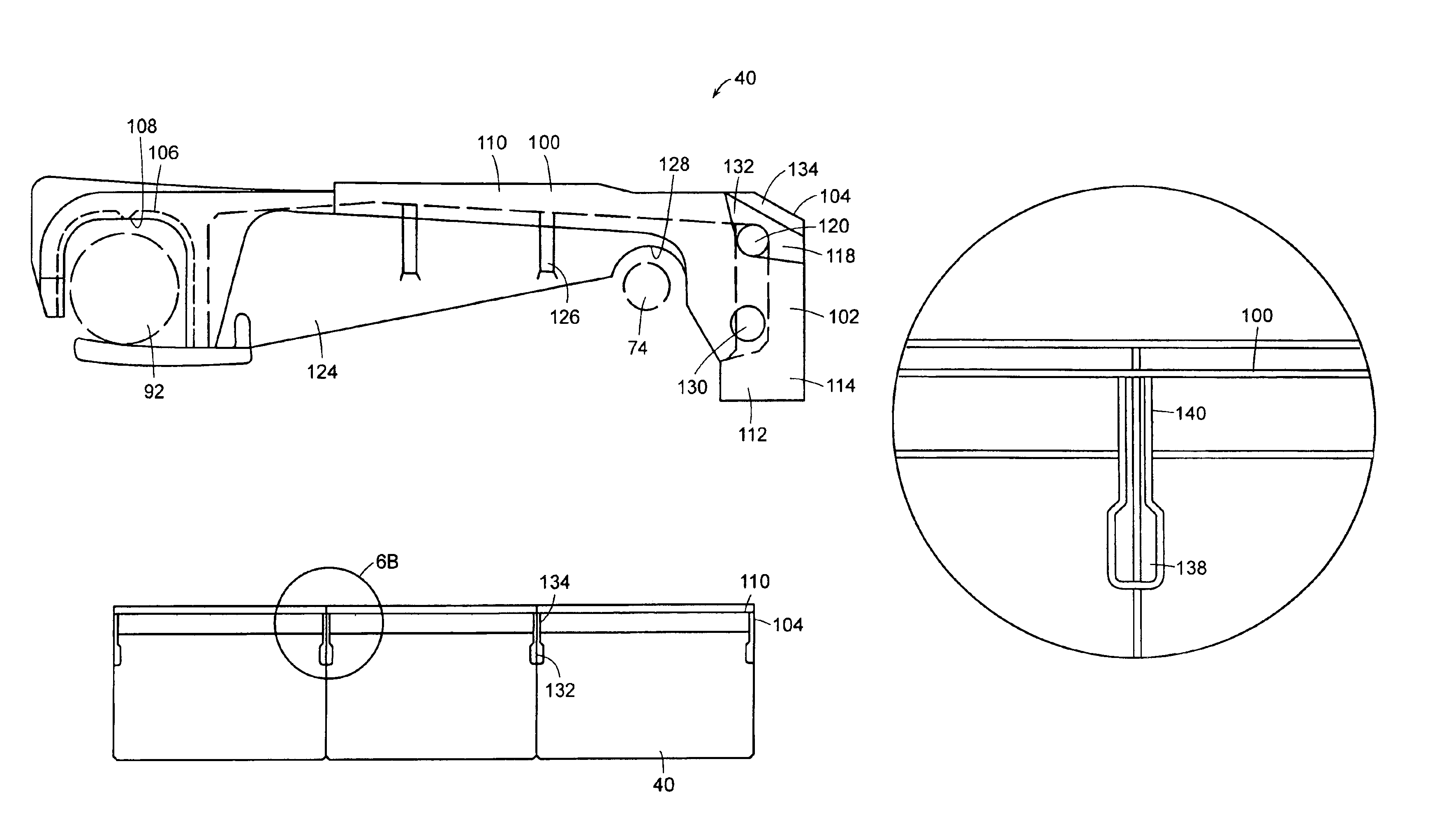
[0037]Referring to the drawings in detail, there is illustrated a grate block in accordance with the present invention designated generally as 40. In a preferred embodiment, the grate block according to the invention directs air flow to allow for generally uniform burning of trash or refuse without thermal stress caused by intense combustion and cooling.

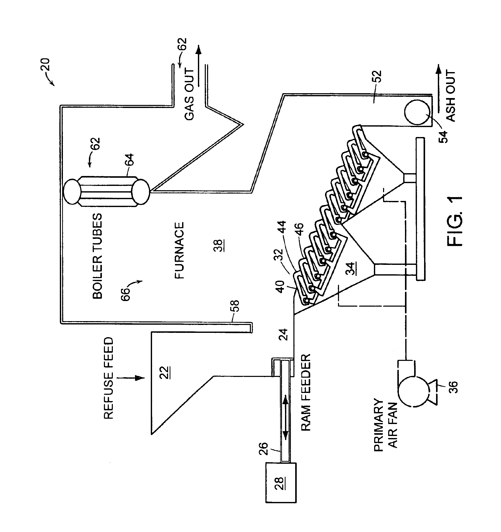
[0038]Referring to FIG. 1, a combustion furnace 20 has trash, also referred to as refuse or fuel, fed via a refuse feed chute 22. The trash is typically not homogeneous and can include wet yard waste, non-combustible material, and high energy content or caloric material. The trash drops upon a feed table 24, on which a pusher ram 26 is moved back and forth by a drive 28.

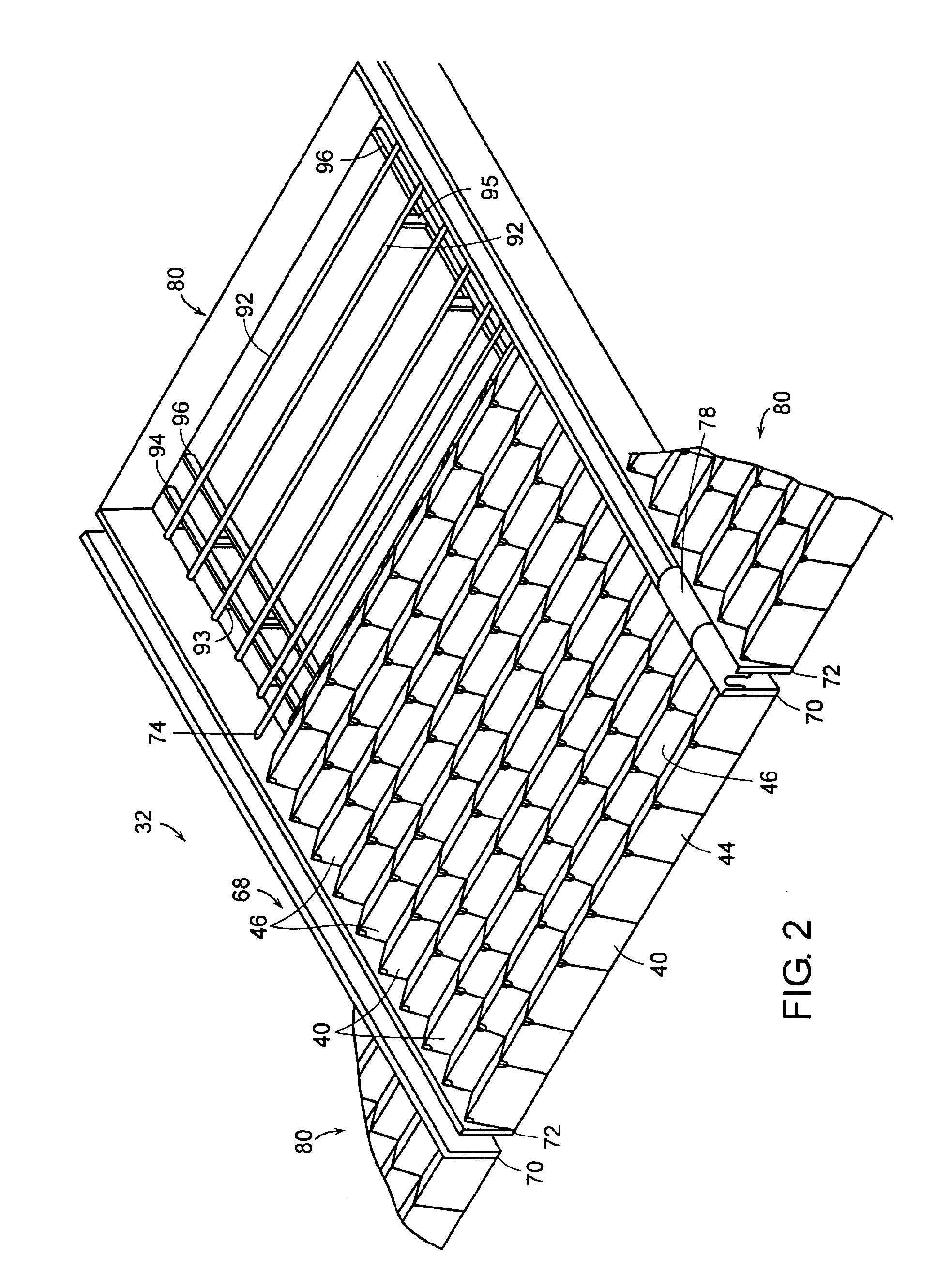
[0039]The feed table 24 is adjoined at the same height by the start of a grate 32 having a plurality of grate blocks 40 which consists of fixed rows 44 arranged stepwise and movable rows 46 arranged in-between the fixed rows 44. The movable rows 46 are shown in FIG. 1...


PUM


Abstract

A grate block for an incinerator has a top wall and a front wall that extends from the front wall. A pair of side walls wherein each sidewall extends from the top wall and the front wall. Each of the side walls of the grate blocks engage the side wall of the adjacent grate block. Each side wall has a recess in proximity to the front wall/upper wall interface. The recess defines a gap between the side walls of the adjacent grate blocks. An opening in the recess through the side wall allows for the flow of air from a cavity within the grate block. The slot created by the recess of the two adjoining grate blocks has a narrower slot opening created by a shallow upper recess and a broader slot opening created by a deeper lower recess. In that the openings are not directly aligned with any of the exposed surfaces, the air is required to make a perpendicular turn prior to exiting the recess of the grate block. This allows for sufficient pressure to drop across the surface of the grate block for a uniform distribution of primary air. Furthermore, the pressure drop makes it difficult to plug the opening with ash and debris by the change in direction. Furthermore, the deeper lower recess below the shallow upper recess creates a self-relieving channel.

Description

BACKGROUND OF THE INVENTION[0001]As a result of changes in the composition of refuse or garbage, and particularly due to the increase in caloric value of such material, the combustion grate is exposed to high thermal stresses, particularly certain individual portions thereof. Furthermore, the operator of municipal waste mass burning applications typically has no control over the composition of the trash being fed into the system. At any given moment, one section of the grate can have a pile of wet yard waste while another section can have bags of high caloric or energy content plastic containers.[0002]Due to the dual function of the combustion grate as a combustion support with ventilating means and also as a transfer or conveyance means for the material to be burned, the grate structure often includes such features as alternating fixed and movable grate sections and is a relatively complex multi-part structure. By having a uniform distribution of air beneath the grate, the basic de...

Claims


Application Information

Patent Timeline
Patent Type & Authority Patents(United States)
IPC IPC(8): F23H1/00F23H1/02F23H7/00F23H11/00F23H17/12F23G5/00F23H3/00F23H17/00F23H3/04F23H11/12F23H7/08F23H7/18
CPCF23G5/002F23H1/02F23H3/04F23H7/08F23H7/18F23H11/12F23H17/12
Inventor HEPP, MARK P.
Owner HEPP MARK P
Why Eureka
Try Eureka