
Methods and apparatus for analyzing high voltage circuit breakers

Inactive Publication Date: 2005-11-15
MEGGER SWEDEN
View PDF17 Cites 19 Cited by
  • Summary
  • Abstract
  • Description
  • Claims
  • Application Information

AI Technical Summary

Benefits of technology

[0006]In another aspect, a computer program embodied on a computer readable media for analyzing circuit breakers is provided. The program includes a software code segment programmed to determine a circuit breaker contact closing time, determine a circuit breaker contact opening time, and determine a circuit breaker pre-insertion resistor resistance value using three voltage samples and three current samples that facilitate minimizing an induced current measurement error.

Problems solved by technology

During operation, inrush currents with relatively large magnitudes may cause damage to the circuit.
However, with a pre-insertion resistor installed, the initial inrush current may reach values of only about 2 to 4 thousand amperes.
If the circuit breaker is switching capacitor banks, the banks discharge directly through the contacts, such that the current is limited by the surge impedance of the banks and the bus work.
However, such testing is typically performed in place, for example, in a switchyard or substation where the circuit breaker is normally located, and may subject testing equipment to power line frequency interference from voltages induced into test equipment components and / or cabling from power lines located proximate the circuit breaker and testing equipment.
Additionally, when timing a circuit breaker in a substation with high voltage lines surrounding the circuit breaker being tested, a power line frequency current flow may be undesirably induced into the measurement circuits due to capacitive coupling between the test object and adjacent high voltage lines.
The interference current may be of substantially the same frequency as the desired measurement result, therefore adversely affecting the measurement result.

Method used


Image

  • Methods and apparatus for analyzing high voltage circuit breakers
  • Methods and apparatus for analyzing high voltage circuit breakers
  • Methods and apparatus for analyzing high voltage circuit breakers

Examples


Embodiment Construction

[0013]Periodic testing of circuit breakers may include performing a contact timing test and a pre-insertion resistor resistance test. The timing test measures an elapsed time from the initiation of movement of circuit breaker contacts until the main circuit current stops flowing during an opening test, and also an elapsed time from an initiation of movement of the contacts until the main circuit current starts flowing during a closing test. The pre-insertion resistor resistance test measures the value of the pre-insertion resistor.

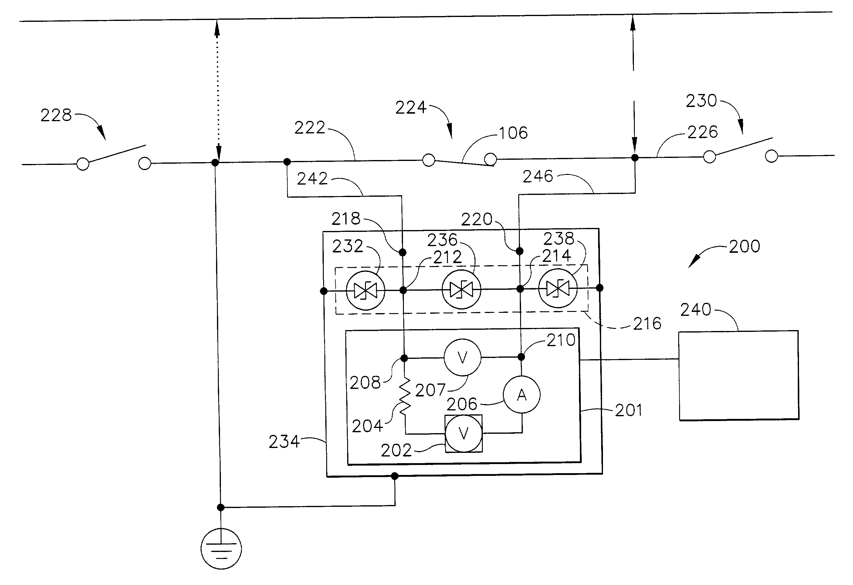
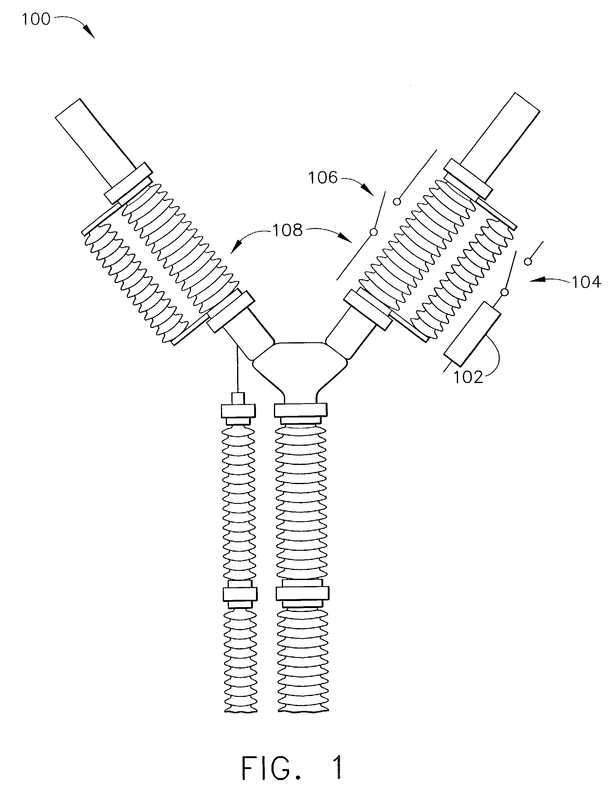
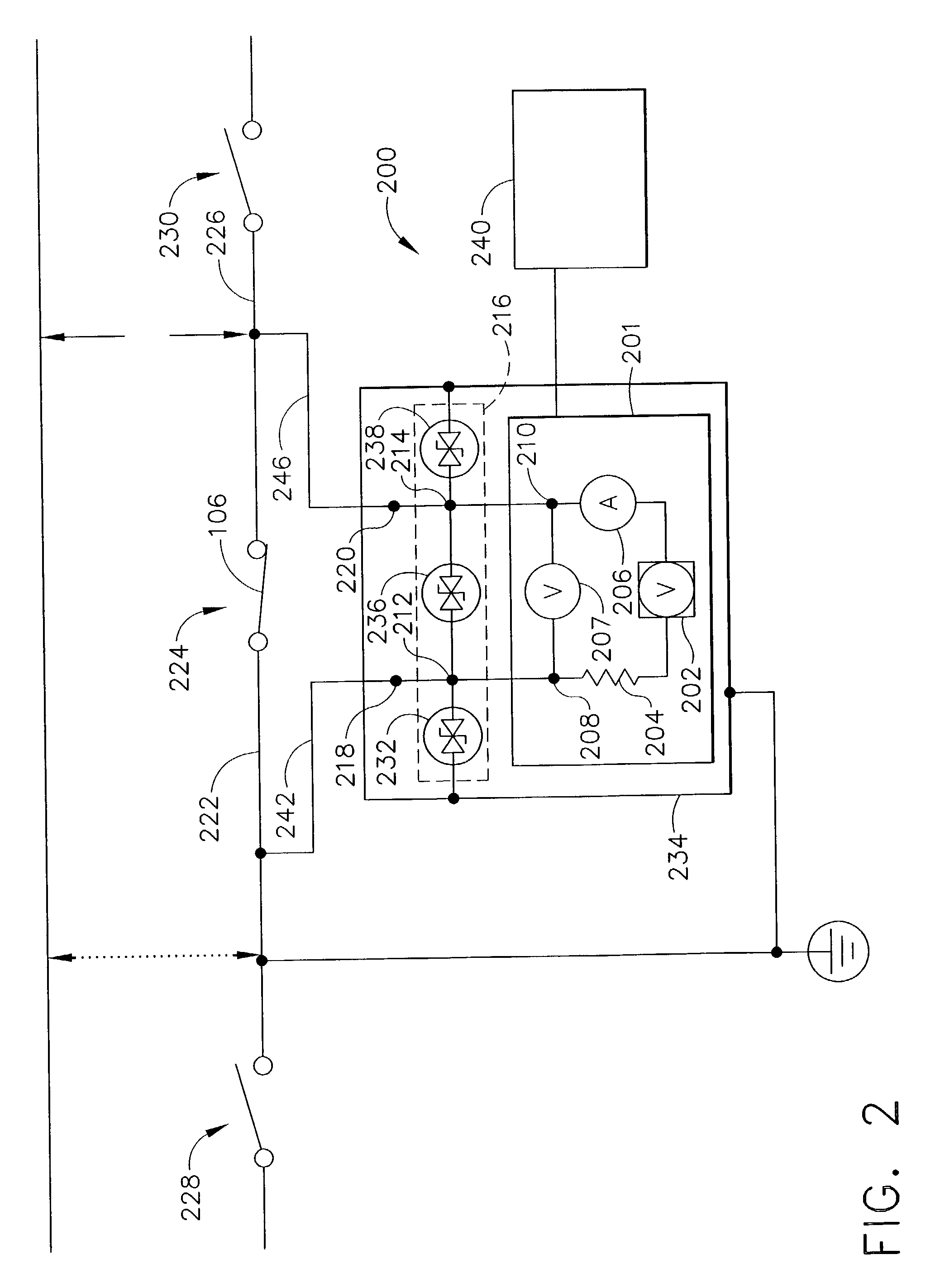
[0014]FIG. 1 is a schematic illustration of an exemplary high voltage circuit breaker phase 100. A high voltage circuit breaker (not shown) may include a pre-insertion resistor 102 and a moving resistor contact 104 electrically coupled in parallel with a moving main contact 106. In the exemplary embodiment, phase 100 includes two breaks 108 that each include a pre-insertion resistor (only one is shown in FIG. 1).

[0015]In operation, when the circuit breaker...


PUM


Abstract

Methods, computer program segment and apparatus for analyzing high voltage circuit breakers are provided. The method includes determining a circuit breaker contact closing time, determining a circuit breaker contact opening time, and determining a circuit breaker pre-insertion resistor resistance value using at least three voltage samples and three current samples to facilitate reducing an induced current measurement error. The computer program segment is embodied on a computer readable media and is programmed to determine a circuit breaker contact closing time, determine a circuit breaker contact opening time, and determine a circuit breaker pre-insertion resistor resistance value using at least three voltage samples and three current samples that facilitate minimizing an induced current measurement error. The apparatus includes a testing circuit, an overvoltage protection circuit, and a processor programmed to determine a circuit breaker contact timing measurement and a circuit breaker contact resistance measurement.

Description

BACKGROUND OF THE INVENTION[0001]This invention relates generally to high voltage circuit breakers, and more specifically to methods and systems for analyzing circuit breaker contacts.[0002]At least some known circuit breakers, use a pre-insertion resistor to facilitate protecting circuits during closing operations of the circuit breaker. Specifically, as the circuit breaker is closed, the pre-insertion resistor is connected in parallel with a gap defined between the open circuit breaker contacts. More specifically, when the pre-insertion resistor is placed in parallel with the gap, the circuit voltage measured to ground (generally line-to-ground voltage) is dropped across the resistor. Accordingly, the current flowing through the resistor is determined by V / Z, wherein V represents the line-to-ground voltage of the circuit and Z represents the vector sum of the resistance of the pre-insertion resistor and the surge impedance of inductive and capacitive elements, such as capacitor ba...

Claims


Application Information

Patent Timeline
IPC IPC(8): G01R13/14G01R13/00G01R31/02G01R31/327
CPCG01R31/3274
Inventor RUDHOLM, STIG OLOVWACKLEN, NILS FREDRIK
Owner MEGGER SWEDEN
Learn More