
Flexible multiplexer/demultiplexer and method for transport of optical line data to a wide/metro area link

Inactive Publication Date: 2005-11-15
CIENA
View PDF16 Cites 17 Cited by
  • Summary
  • Abstract
  • Description
  • Claims
  • Application Information

AI Technical Summary

Benefits of technology

[0008]Further in accordance with the invention is a method for multiplexing client data for transport from an optical serial link to a clear optical channel comprising N STS-1s of a metro or wide area link. Data for 1 to n clients is mapped, according to a predetermined bandwidth allocation, to an N×STS-1 SONET payload using the allocated STS-1s for each client whereby the allo

Problems solved by technology

However, these protocols were designed for in-building IT server room requirements and are not suitable for metropolitan (wide) area networks which extend over much greater distances.
The use of these protocols over such greater distances imposes several challenges on the infrastructure of the metro area network including the need to accommodate Gbps transport rates with no packet loss and very low latency (delay).
Disadvantageously, however, the cost of such networks is high and the number of customers they are able to serve is limited to the number of wavelengths deployed in the network.
Other possible available options include the use of IP or ATM packet switching methods but IP switching inherently drops packets in an overload situation and, further, its transport protocols are relatively heavyweight.
ATM switching is also of high cost and is not able to scale well in the Gbps data rate range required for storage traffic.
Disadvantageously, the head of line blocking which results from the use of packet routers causes jitter at Gbps data rates.
Further, if a normally switched SONET network is used it is necessary to include large realignment buffers at each end (to account for a differing delays incurred by different STS-1s due to different flow paths) and such buffers introduce undesirable latency (i.e. large transmission delays).

Method used


Image

  • Flexible multiplexer/demultiplexer and method for transport of optical line data to a wide/metro area link
  • Flexible multiplexer/demultiplexer and method for transport of optical line data to a wide/metro area link
  • Flexible multiplexer/demultiplexer and method for transport of optical line data to a wide/metro area link

Examples


Embodiment Construction

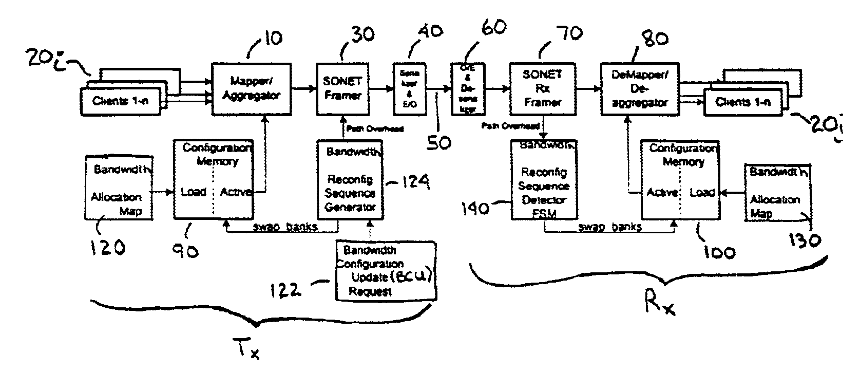
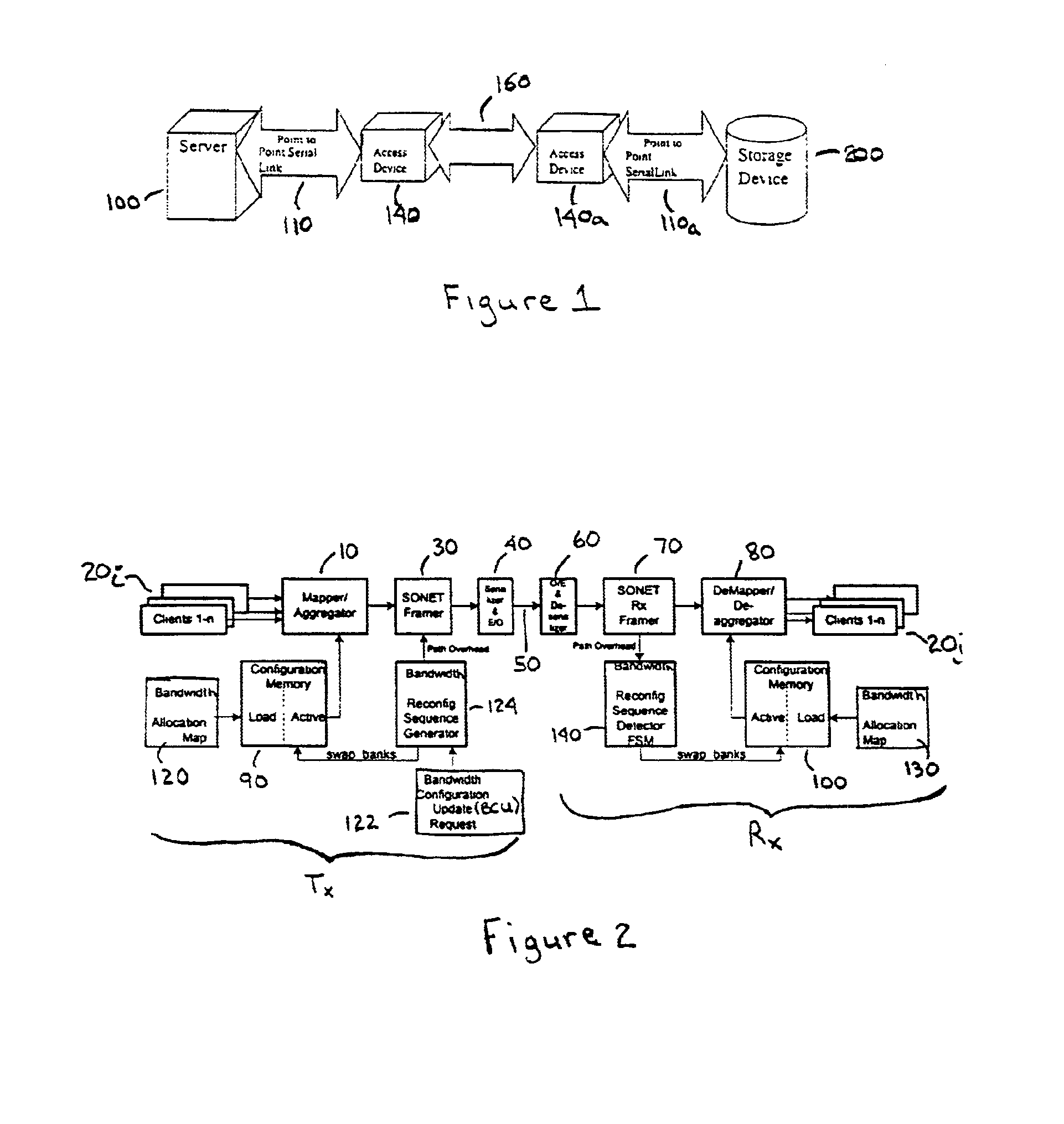
[0021]FIG. 1 of the drawings is a schematic block diagram illustrating an exemplary data transport system, from a server (external device) 100 to a storage device 200 (remote device), in which the flexible bandwidth management method and apparatus of the present invention is used at the access devices 140, 140a. In this example the server 100 transports data over a high speed optical point-to-point serial link 110 to the access device 140. The access device 140 controls the flow of the data and multiplexes the data on the basis of a flexibly assigned bandwidth allocation for that external device for output onto a metro or wide area fiber transport link 160. At the remote end of the data transport system a similar access device 140a receives data from the metro / wide area link 160 and demultiplexes and outputs the data onto another high speed optical point-to-point link 110a for transport to the storage device 200. For the reverse data transport direction the access device 140a receiv...


PUM


Abstract

A method and apparatus are provided for flexible time-division multiplexing, and demultiplexing, of serial line data, from 1-n client lines, based on the SONET standard (e.g. OC-48 or OC-192) whereby a predetermined and reconfigurable number of STS-1s are allocated to each client. A multiplexer includes 1 to n mappers for mapping the data of 1 to n clients, according to a predetermined bandwidth allocation, to an N×STS-1 SONET payload, each mapper using y STS-1s where y is 0 to N, the y STS-1s being selected on a sequential or non-sequential concatenation basis from the N STS-1s. Each mapper maps the data of one client and each allocated STS-1 is allocated to one client and the total number of STS-1s allocated to the clients is less than or equal to N. An aggregator aggregates the mapped data into a composite STS payload comprising N STS-1s. A bandwidth allocation receiver receives the bandwidth allocation. The bandwidth allocation may be received from a source external to the multiplexer and the source may be a network controller. A demultiplexer includes a deaggregator for deaggregating the STS payload to provide the mapped data for the clients. 1 to n demappers demap the client data according to the predetermined bandwidth allocation. A bandwidth allocation receiver receives the bandwidth allocation.

Description

FIELD OF THE INVENTION[0001]This invention relates to a method and apparatus for transporting optical line data, such as from a fiber channel (FC) or Gigabit Ethernet (GbE) interface, to a fiber metropolitan or wide area network (MAN / WAN) and, more specifically, to a multiplexer / demultiplexer for flexibly managing bandwidth over such a network.BACKGROUND OF THE INVENTION[0002]The transport of optical line data from an enterprise server to a remote device such as a storage device (such as to extend the storage area network to enable storage service providers to offer out-sourced storage services to the enterprise) is presently predominantly based on I / O channel protocols such as FC1, GbE and ESCON. However, these protocols were designed for in-building IT server room requirements and are not suitable for metropolitan (wide) area networks which extend over much greater distances. The use of these protocols over such greater distances imposes several challenges on the infrastructure of...

Claims


Application Information

Patent Timeline
IPC IPC(8): H04J3/16H04L12/24H04Q11/04H04J3/00
CPCH04J3/1617H04L41/0896H04J2203/0067H04J2203/0082H04J2203/0091Y10S370/907
Inventor BISSON, GERMAIN PAULADOLPH, STEPHEN KIERAN ANTHONYFRANK, RONALD ARTHURKNOBEL, STEPHENYAU, JIM CHI-LUENPELLEY, BARRY LEO
Owner CIENA
Learn More