

Estimation of oil-diluting fuel quantity of engine
a technology of oil-diluting fuel and engine, which is applied in the direction of machines/engines, electric control, auxilary lubrication, etc., can solve the problems of receiving adverse influence of such fuel on engine operation
- Summary
- Abstract
- Description
- Claims
- Application Information
AI Technical Summary
Benefits of technology
Problems solved by technology
Method used
Image

Examples
first embodiment
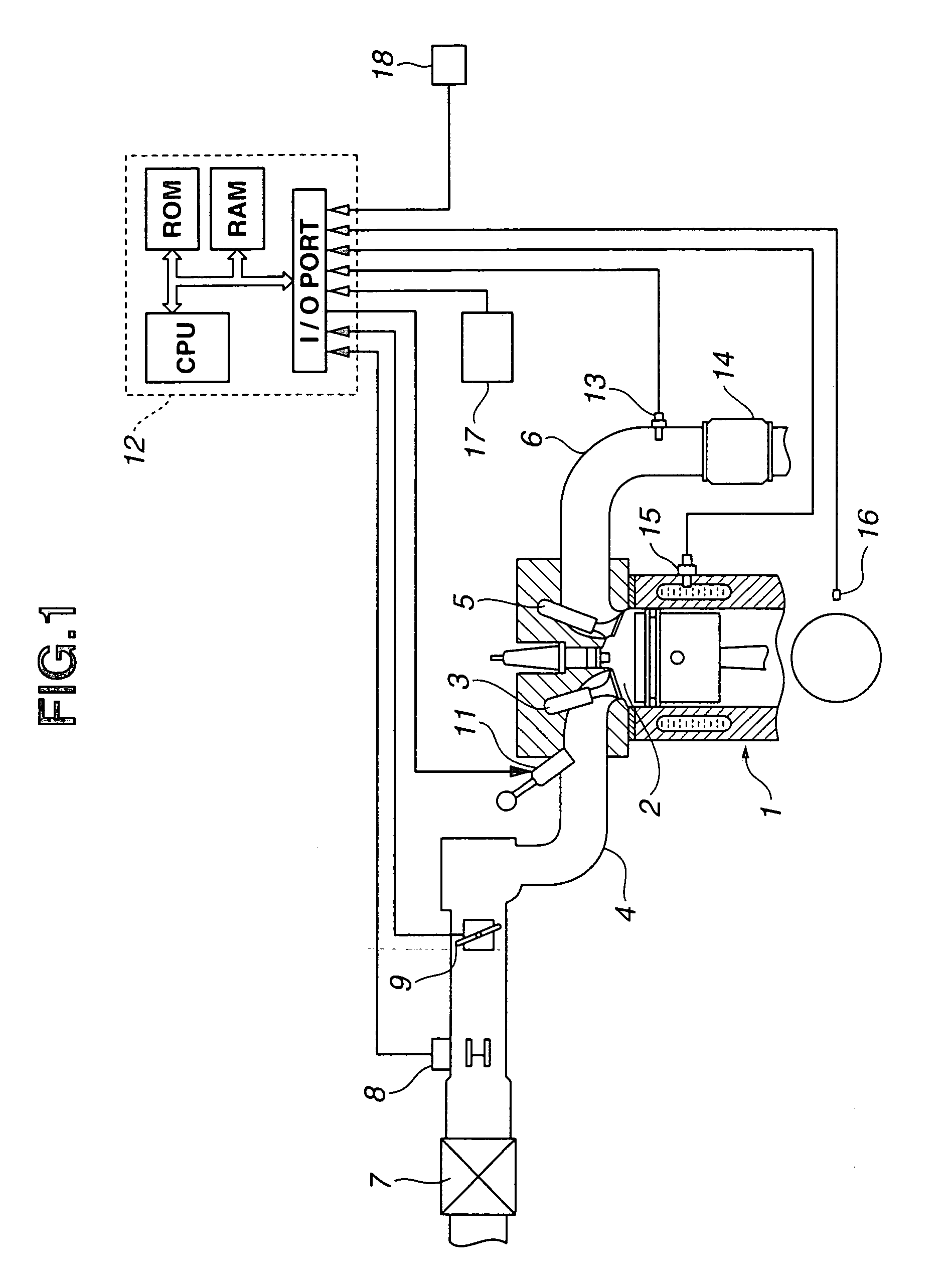
[0032]FIG. 1 shows an engine system according to the present invention.
[0033]An engine main block 1 includes at least one combustion chamber 2 with which an intake passage 4 is connected through an intake valve 3, and an exhaust passage 6 is connected through an exhaust valve 5.
[0034]In intake passage 4, there are provided an air cleaner 7, an air flowmeter 8 for sensing an intake air quantity, a throttle valve 9 for regulating the intake air quantity, and a fuel injector 11 for injecting fuel in the intake air.
[0035]An engine control unit (ECU) 12 produces a fuel injection command signal, and commands fuel injector 11 to inject fuel into the intake air to achieve a desired air fuel ratio in accordance with engine operating conditions.
[0036]In exhaust passage 6, there are provided an oxygen sensor 13 for sensing an oxygen concentration in the exhaust gas mixture, and a three-way catalyst 14. Three-way catalyst 14 can convert harmful emissions of hydrocarbons, carbon monoxide, and ox...
third embodiment
[0078]Alcohol fuel requires a large amount of fuel injection as compared to gasoline to obtain a given equivalence ratio because of the numbers of atoms of C (carbon), H (hydrogen) and O (oxygen). Therefore, an engine system is arranged to predict the alcohol concentration of fuel accurately as quickly as possible, by utilizing the output signal of oxygen concentration sensor 13.
[0079]Earlier technology of estimating an alcohol concentration from a deviation of an equivalence ratio is insufficient in accuracy and speed of estimation, especially when fuel of a different kind is replenished. In this technology, the influence of fuel evaporated from the oil lingers, and deteriorates the accuracy of engine control based on the estimated alcohol concentration. For example, the ignition timing control is insufficient because of difference in combustion speed of fuel, and the air fuel ratio control is unsatisfactory especially in a transient state because of inadequacy in wall flow correc...
fourth embodiment
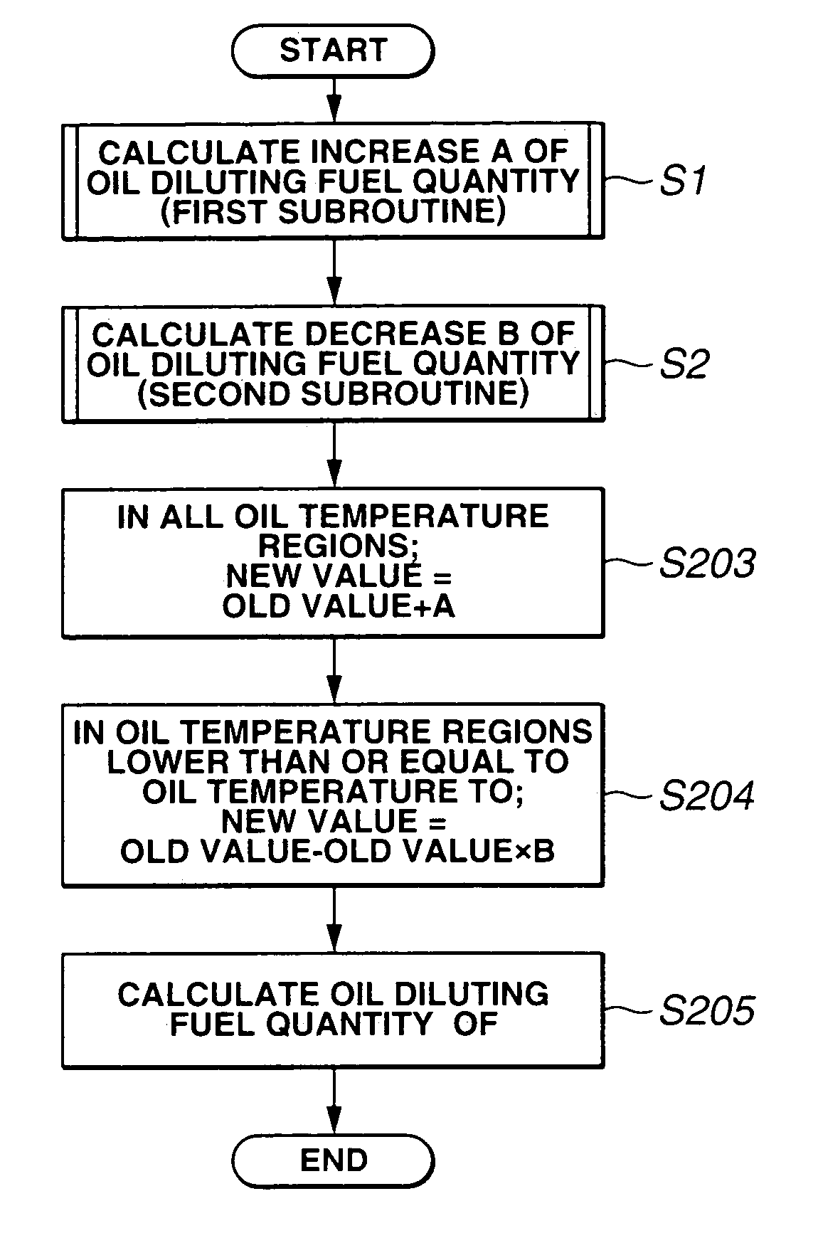
[0094]FIG. 19 shows a process for determining an oil-diluting fuel quantity OF, according to the present invention. This process is performed at regular time intervals of a predetermined time length.
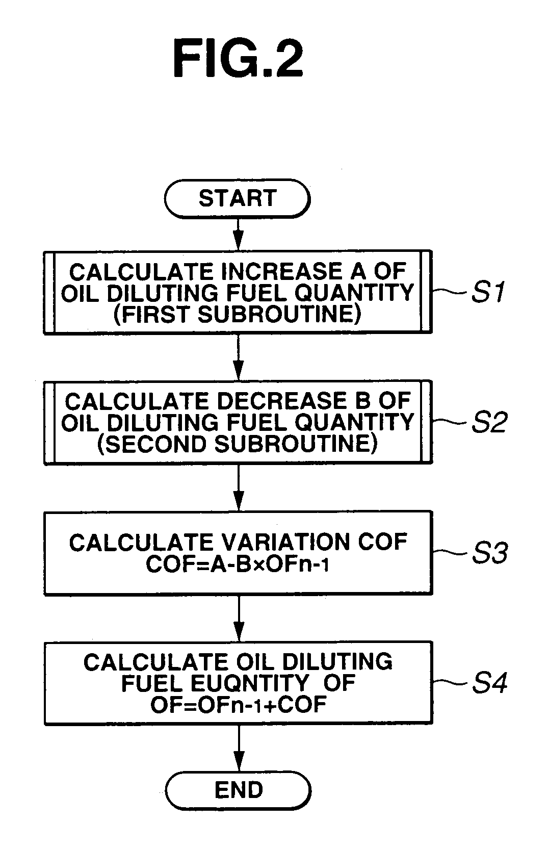
[0095]Steps S1 and S2 of FIG. 19 are substantially identical to S1 and S2 shown in FIG. 2. Step S1 calculates the increase quantity (or increase) A of an oil-diluting fuel quantity according to the first subroutine as mentioned before. Step S2 calculates the decrease rate (the rate of evaporation) B of the oil-diluting fuel quantity according to the second subroutine as mentioned before.
[0096]Steps S203 and S204 are arranged to update the contents (indicators) of an oil-diluting fuel quantity table TOF arranged in accordance with the oil temperature TO, by using the increase quantity A determined at S1 and the decrease rate B determined at S2.
[0097]FIG. 20 is a graph for illustrating the oil-diluting fuel quantity table TOF schematically. In this example, a plurality of oil temperature r...
PUM
 Abstract
Description
Claims
Application Information