Inkjet printhead, driving method of inkjet printhead, and substrate for inkjet printhead

a technology of inkjet printing and inkjet printing, which is applied in the direction of printing, other printing apparatus, etc., can solve the problems of generating leakage current, unable to withstand the intense electric field, and unable to withstand the pressure required as a switch device, and achieves the effect of simple structur

Inactive Publication Date: 2005-11-22
CANON KK
View PDF23 Cites 23 Cited by
  • Summary
  • Abstract
  • Description
  • Claims
  • Application Information

AI Technical Summary

Benefits of technology

[0028]The present invention has been proposed to solve the conventional problems, and has as its object to provide a low-cost and easy-to-control inkjet printhead having plural types of printing elements, which discharge relatively different amounts of ink, in a simple structure.
[0034]By virtue of this configuration, even in a case where the printhead is constructed with first and second printing elements which discharge relatively different amounts of ink and are arranged on the same array, for instance, assuming that the number of the first printing elements and the number of the second printing elements are the same, the number of print data inputted at once becomes half the number of all printing elements. Therefore, the amount of data stored and held is cut down to half the number of printing elements. Also, printing performed by the first or second printing element can be realized with simple driving control.
[0035]Therefore, it is possible to reduce the cost of the inkjet printhead having plural types of printing elements, which discharge relatively different amounts of ink, and possible to easily control driving of the printhead.
[0044]By virtue of the above configuration, a selection signal (data) for changing the amount of discharge can be transmitted in the similar manner to print data. Therefore, it is possible to reduce the number of signal terminals.
[0045]Accordingly, it is possible to reduce the cost of the inkjet printhead having plural types of printing elements, which discharge relatively different amounts of ink, and possible to easily control driving of the printhead.

Problems solved by technology

However, if the conventional MIS-type field effect transistor 930 is used under a large electric current which is necessary for driving the electrothermal transducers, the p-n reverse bias junction between the drain and well cannot withstand the intense electric field, generating a leak current.
Therefore, it cannot withstand the pressure required as a switch device.
Furthermore, if the MIS-type field effect transistor serving as a switch device has a large resistance when it is turned on, an unnecessary current is consumed.
Therefore, a current necessary for driving the electrothermal transducers cannot be obtained.
Therefore, it raises a problem of an enlarged size of the substrate to be solved.
However, in a case of employing an inkjet printhead where one heater is provided for one discharge orifice, it is difficult to change the ink discharge amounts in multi-levels to be discharged from one orifice.
Furthermore, if the configuration where plural heaters are provided for one discharge orifice is adopted to change the ink discharge amounts in multi-levels, the circuit formed on the substrate of the inkjet printhead becomes complicated, because the number of heaters and driving circuits thereof becomes as many as multiple times of the number of discharge orifices, and the driving circuits for the plural heaters should be localized for each discharge orifice in layout.
As a result, the cost of the printhead increases.

Method used


Image

  • Inkjet printhead, driving method of inkjet printhead, and substrate for inkjet printhead
  • Inkjet printhead, driving method of inkjet printhead, and substrate for inkjet printhead
  • Inkjet printhead, driving method of inkjet printhead, and substrate for inkjet printhead

Examples


first embodiment

[First Embodiment]

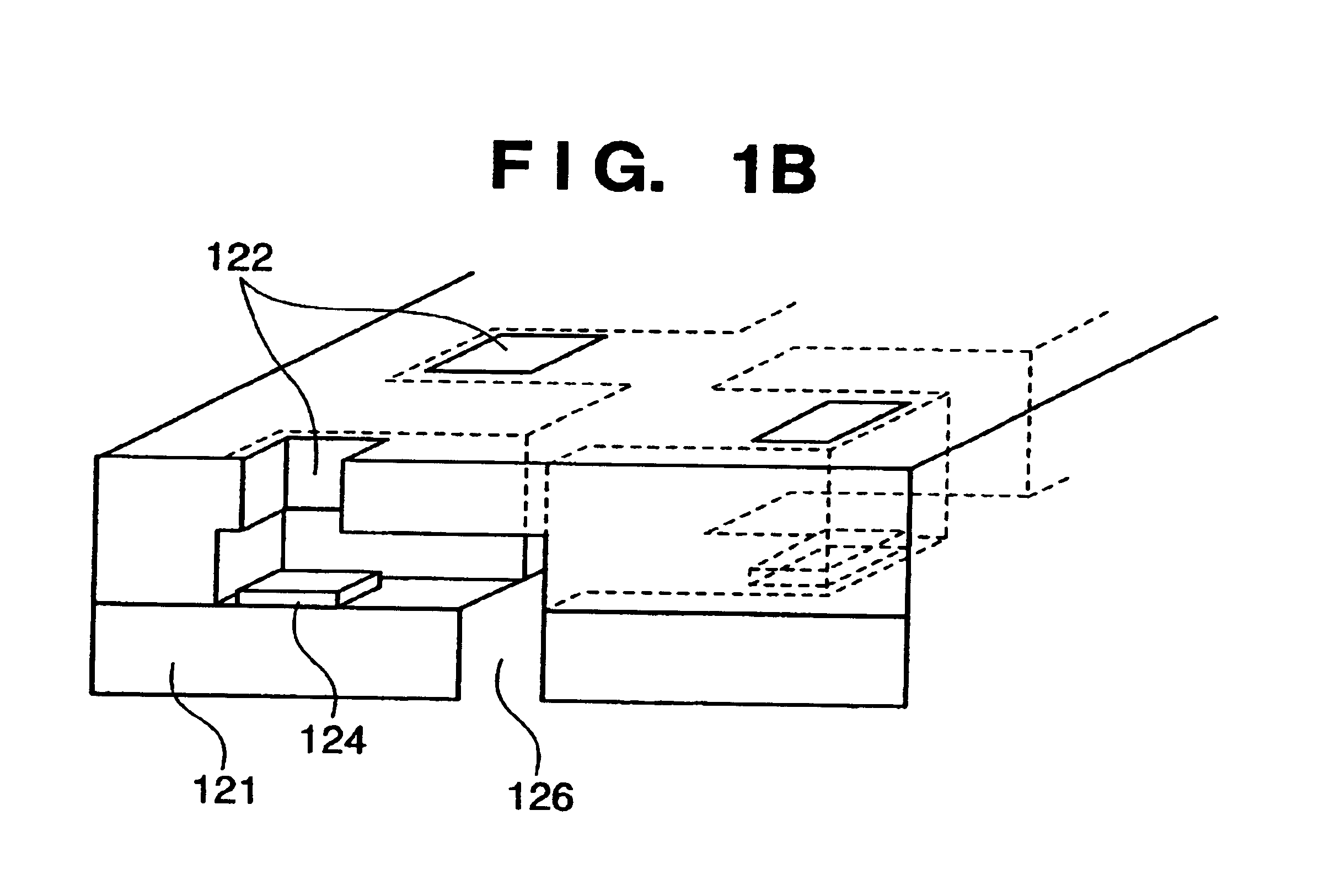
[0102]FIG. 1B is a schematic sectional view for describing a configuration of the first embodiment of the inkjet printhead employed in the above-described printer. In an ink channel communicating with discharge orifices 122, heating elements (heaters) 124 respectively corresponding to the discharge orifices 122 are provided. When predetermined energy is applied to the heaters 124 by the head driving circuit, film boiling causes a change of state in ink, i.e., a foaming phenomenon, thereby discharging ink droplets from the discharge orifices 122.

[0103]Note that the heaters 124 are formed on the silicon substrate 121 by a technique similar to the semiconductor process. Numeral 126 denotes an ink supply port for supplying ink to each of the discharge orifices from a rear side of the element board.

[0104]FIG. 2 shows an array of discharge orifices of the printhead according to the first embodiment. To discharge two different types of ink droplets: large and small ink dr...

second embodiment

[Second Embodiment]

[0118]Hereinafter, the second embodiment of the inkjet printhead according to the present invention is described. With respect to the components similar to that of the first embodiment, descriptions thereof are omitted, and characteristic portions of the second embodiment are mainly described.

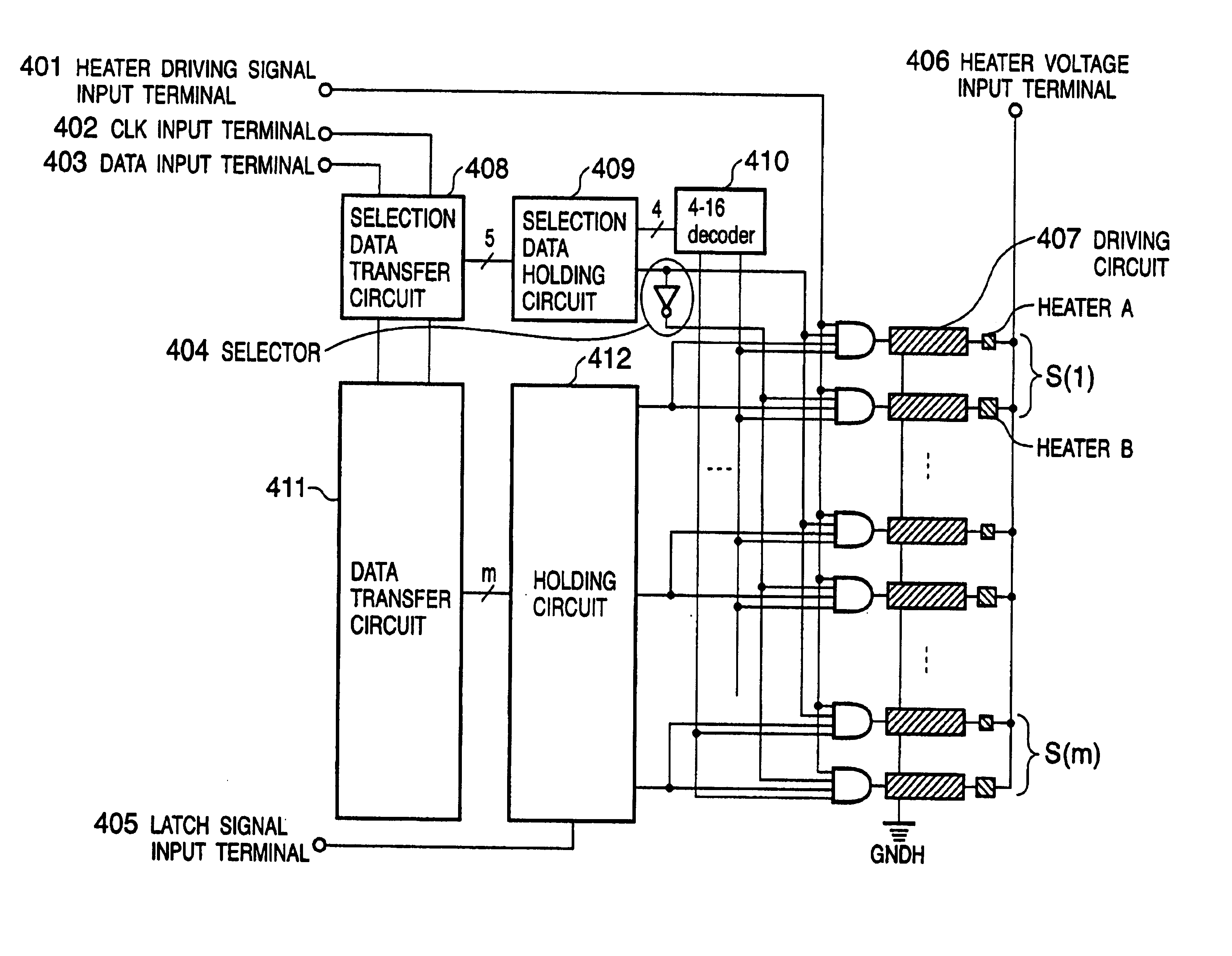
[0119]FIG. 8 is a block diagram showing a configuration of a driving circuit of a printhead according to the second embodiment. FIG. 9 is a timing chart showing a state of each signal shown in FIG. 8.

[0120]The printhead according to the second embodiment also has 32 discharge orifices having a similar array as that of the first embodiment. The configuration of the driving circuit shown in FIG. 8 is substantially the same as that of the first embodiment shown in FIG. 3. The selector 86, 2-to-4 decoder 87, AND gates 810, and heat drivers 811 in FIG. 8 respectively correspond to the selector 36, 2-to-4 decoder 37, AND gates 310, and heat drivers 311 in FIG. 3. The input / output c...

third embodiment

[Third Embodiment]

[0125]Hereinafter, the third embodiment of the inkjet printhead according to the present invention is described. With respect to the components similar to that of the first and second embodiments, descriptions thereof are omitted, and characteristic portions of the third embodiment are mainly described.

[0126]FIG. 10 is a block diagram showing a configuration of a driving circuit of the printhead according to the third embodiment. FIG. 11 is a timing chart showing a state of each signal shown in FIG. 10.

[0127]The printhead according to the third embodiment also has 32 discharge orifices having a similar array as that of the first and second embodiments. The configuration of the driving circuit shown in FIG. 10 is substantially the same as that of the second embodiment shown in FIG. 8. The 2-to-4 decoder 107, AND gates 1010, and heat drivers 1011 in FIG. 10 respectively correspond to the 2-to-4 decoder 87, AND gates 810, and heat drivers 811 in FIG. 8. The input / outp...


PUM


Abstract

To drive an inkjet printhead having an array of printing elements, where the first and second printing elements which discharge relatively different amounts of ink are arranged on the same array in a predetermined direction, print data for the first or second printing element is serially inputted, the inputted print data is sequentially stored, the stored print data is latched, a selection signal indicative of which of the first or second printing element is to be driven is inputted, a driving signal indicative of a driving period is inputted, and respective printing elements are driven in accordance with the latched print data, the selection signal, and the driving signal. Accordingly, it is possible to reduce the cost of the printhead having plural types of printing elements, which discharge relatively different amounts of ink, and possible to easily control driving of the printhead.

Description

FIELD OF THE INVENTION[0001]The present invention relates to an inkjet printhead and a driving method of an inkjet printhead, and more particularly, to an inkjet printhead having first and second printing elements which discharge relatively different amounts of ink, and a driving method of the printhead.[0002]Furthermore, the present invention relates to an inkjet printhead, which performs printing by discharging ink by growth and shrinkage of the bubbles in ink caused by heat energy generated by heating resistances, and a substrate for the printhead.BACKGROUND OF THE INVENTION[0003]Inkjet printers are mostly known as printing devices used in printers, copying machines, or the like. Particularly, inkjet printers that employ a method utilizing heat energy as ink discharging energy and discharge ink by bubbles generated by the heat energy have recently come into general use.[0004]An inkjet printhead, used in the above-described inkjet printers, employs an electrothermal transducer (he...

Claims


Application Information

Patent Timeline
Patent Type & Authority Patents(United States)
IPC IPC(8): B41J2/05B41J2/21B41J2/00
CPCB41J2/04528B41J2/04533B41J2/04541B41J2/04543B41J2/04546B41J2/0455B41J2/0456B41J2/04563B41J2/04573B41J2/0458B41J2/14072B41J2/2121B41J2/00
Inventor NAKAJIMA, YOSHINORIMORIYAMA, JIROKANEKO, MINEOWATAYA, MASAFUMIIMANAKA, YOSHIYUKIHATSUI, TAKUYAMOCHIZUKI, MUGATAKEUCHI, SOUTAYAMAGUCHI, TAKAAKIKUBO, KOUSUKE
Owner CANON KK
Why Eureka
Try Eureka