Apparatus for deployment of micro-coil using a catheter

a catheter and catheter applicator technology, applied in the field of intravascular interventional devices, can solve problems such as embolization in the bloodstream, and achieve the effect of reducing the potential for thermal damage of surrounding tissues

Inactive Publication Date: 2005-11-22
MICRUS CORP
View PDF202 Cites 149 Cited by
  • Summary
  • Abstract
  • Description
  • Claims
  • Application Information

AI Technical Summary

Benefits of technology

[0012]Briefly, and in general terms, the present invention provides for an apparatus for deployment of a therapeutic device such as a micro-coil using a catheter by connecting the therapeutic device to a distal portion of a pusher member. In one presently preferred embodiment, the therapeutic device is detachably mounted to the distal portion of the pusher member by a tubular collar that can be heated by a heater to expand the collar and release and deploy the therapeutic device. In another presently preferred embodiment, the therapeutic device is detachably mounted to the distal portion of the pusher member by a connector thread or fiber passing through a heater provided for heating and breaking the connector fiber to release the therapeutic device. In one presently preferred aspect, the heater is advantageously contained substantially within the distal portion of the pusher member, which provides a sufficient amount of thermal insulation to eliminate the potential for thermal damages of surrounding tissues during detachment, and since the connecting fiber is heated and broken at a location fully contained within the distal portion of the pusher member, the potential for releasing undesirable particles of materials into the bloodstream and consequent embolization in the bloodstream is virtually eliminated.

Problems solved by technology

Such devices that release the interventional device by melting or dissolving the intermediate section between the catheter tip and implanted device may cause thermal damage of surrounding tissues during detachment that can cause embolization in the bloodstream, and may also potentially release undesirable particles of materials into the bloodstream that can also cause embolization in the bloodstream.

Method used


Image

  • Apparatus for deployment of micro-coil using a catheter
  • Apparatus for deployment of micro-coil using a catheter
  • Apparatus for deployment of micro-coil using a catheter

Examples


Embodiment Construction

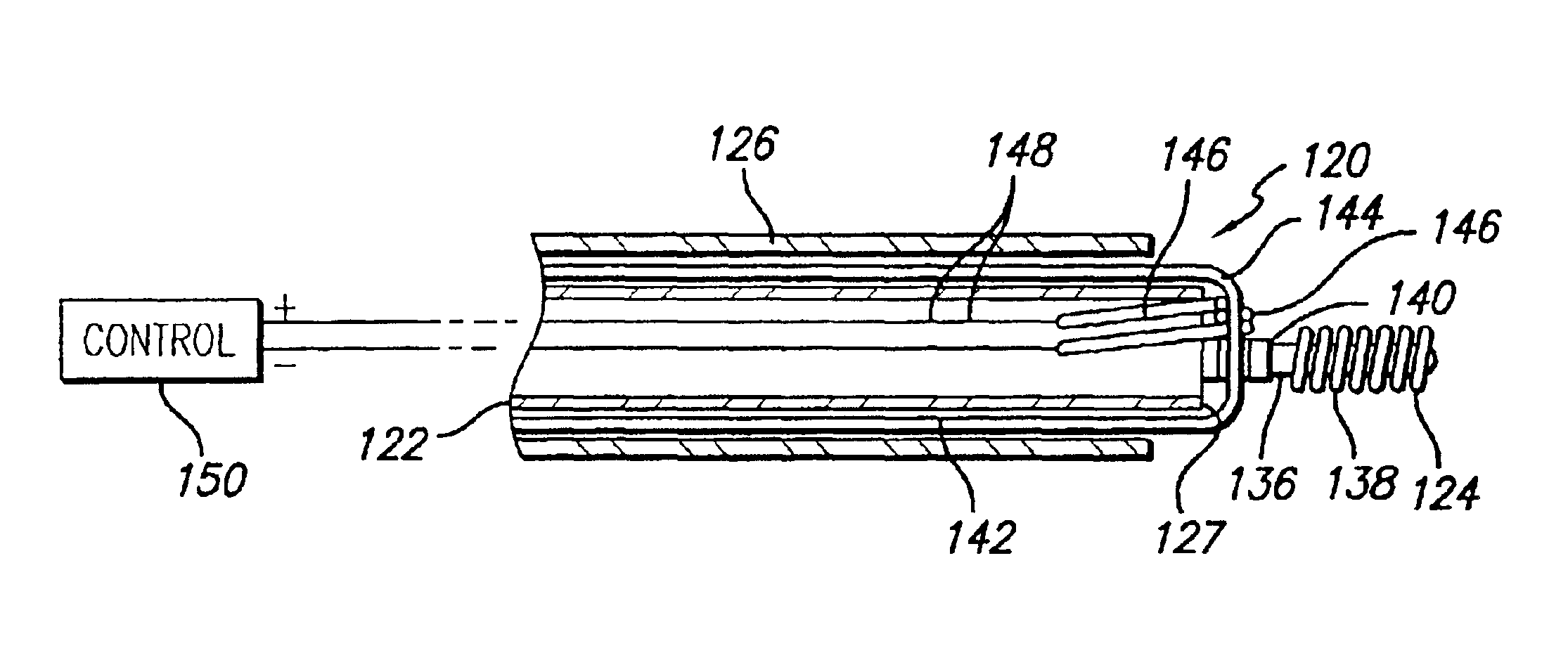
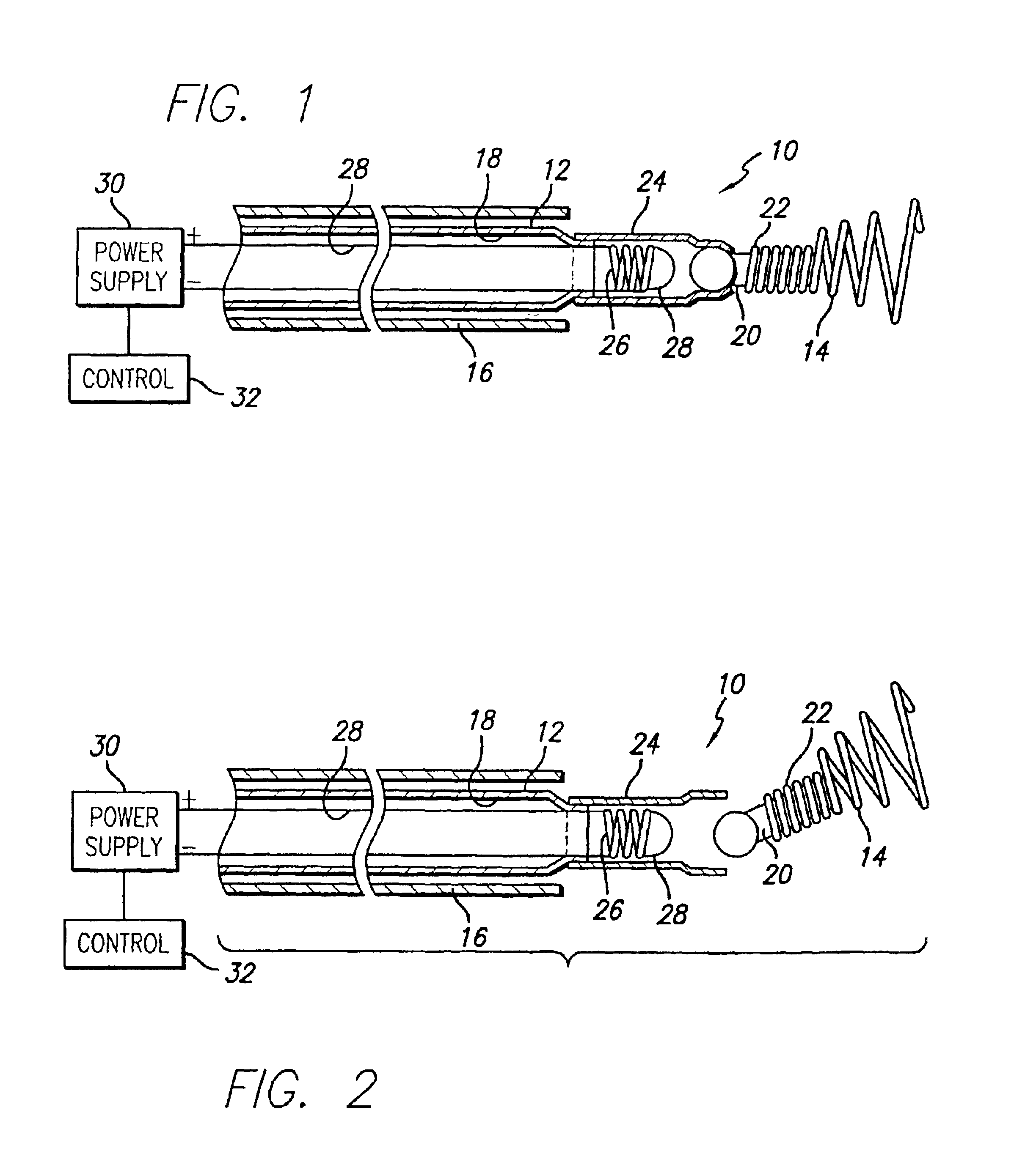
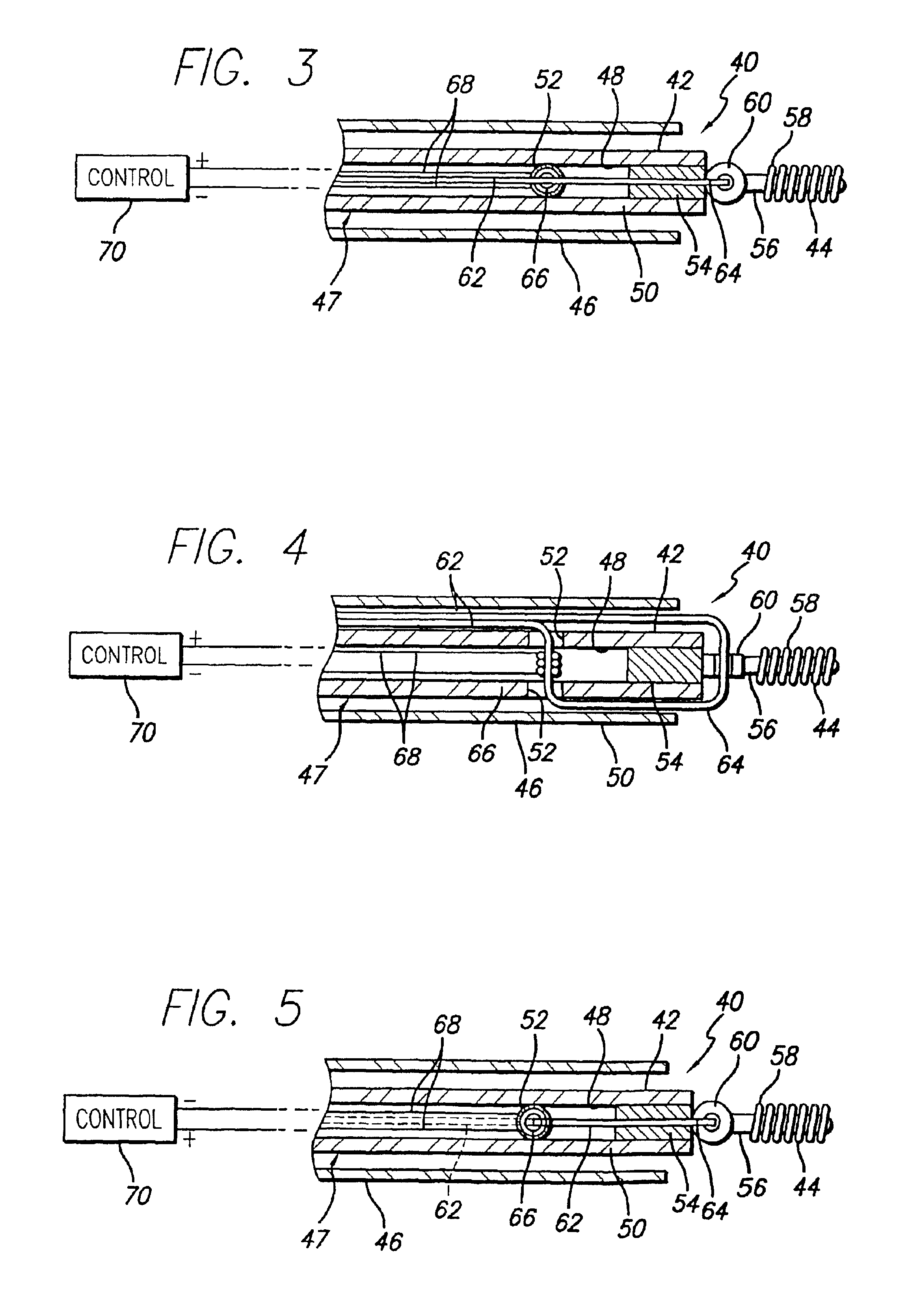
[0029]While vasoocclusive devices have conventionally been delivered to a portion of a patient's vasculature to be treated through a delivery catheter by means of a pusher device, such conventional methods can involve separation of the vasoocclusive device from the pusher device in ways that result in injury to the vasculature, such as by causing thermal damage of surrounding tissues during detachment that can cause embolization in the bloodstream, or by release of undesirable particles of materials into the bloodstream that can cause embolization in the bloodstream.

[0030]As is illustrated in the drawings, in a first presently preferred embodiment, the invention is embodied in an apparatus for deployment of a therapeutic device such as a micro-coil using a catheter by connecting the therapeutic device to a distal portion of a pusher member by a tubular collar that can be expanded by heating a portion of the tubular collar to thereby release the therapeutic device for placement in th...


PUM


Abstract

The apparatus for deployment of a therapeutic device such as a micro-coil detachably mounts the therapeutic device to a distal portion of a pusher member. In one embodiment, the therapeutic device is detachably mounted to the distal portion of the pusher member by a tubular collar that can be heated by a heater such as an electrical resistance coil to expand the collar and release and deploy the therapeutic device. The apparatus for deployment of a therapeutic device such as a micro-coil may also provide for a pusher member and a connector fiber for securing the therapeutic device to the pusher member. The connector fiber passes through a heater within the distal portion of the pusher member, for heating and breaking the connector fiber to release the therapeutic device when a desired placement of the therapeutic device within the vasculature is achieved.

Description

[0001]This is a continuation of Ser. No. 09 / 501,466, filed Feb. 9, 2000, now U.S. Pat. No. 6,478,773.BACKGROUND OF THE INVENTION[0002]1. Field of the Invention[0003]This invention relates generally to devices for interventional therapeutic treatment or vascular surgery for treatment of defects in the vasculature, and more particularly concerns a system and method for delivering intravascular interventional devices, such as for treatment of aneurysms.[0004]2. Description of Related Art[0005]Vascular interventional devices such as vasoocclusive devices are typically placed within the vasculature of the human body by use of a catheter. Vascular interventional devices such as stents can be placed within an occluded vessel to facilitate blood flow through the vessel, and vasoocclusive devices are typically either placed within a blood vessel to block the flow of blood through a vessel making up that portion of the vasculature through the formation of an embolus, or are placed within an a...

Claims


Application Information

Patent Timeline
Patent Type & Authority Patents(United States)
IPC IPC(8): A61B17/12A61F2/06A61B17/00A61F2/84
CPCA61B17/12A61B17/12022A61B17/12113A61B17/12136A61B17/1214A61B2017/00477A61B2017/00867A61B2017/12068A61B2017/1209A61B2018/00005A61B2019/307A61F2002/9505A61F2002/9511A61B2017/12077A61B2090/037
Inventor GANDHI, DEEPAKRAMZIPOOR, KAMAL
Owner MICRUS CORP
Why Eureka
Try Eureka