
SSF/x slow sand filter

a sand filter and slow technology, applied in the direction of filtration separation, moving filter element filter, separation process, etc., can solve the problems of incorrect installation of parts, incorrect assembly of parts, loss of parts in shipment, etc., to reduce the risk of clogging, less head pressure, and larger orifice size

Inactive Publication Date: 2005-11-22
BLACKBURN HUMPHREY
View PDF5 Cites 7 Cited by
  • Summary
  • Abstract
  • Description
  • Claims
  • Application Information

AI Technical Summary

Benefits of technology

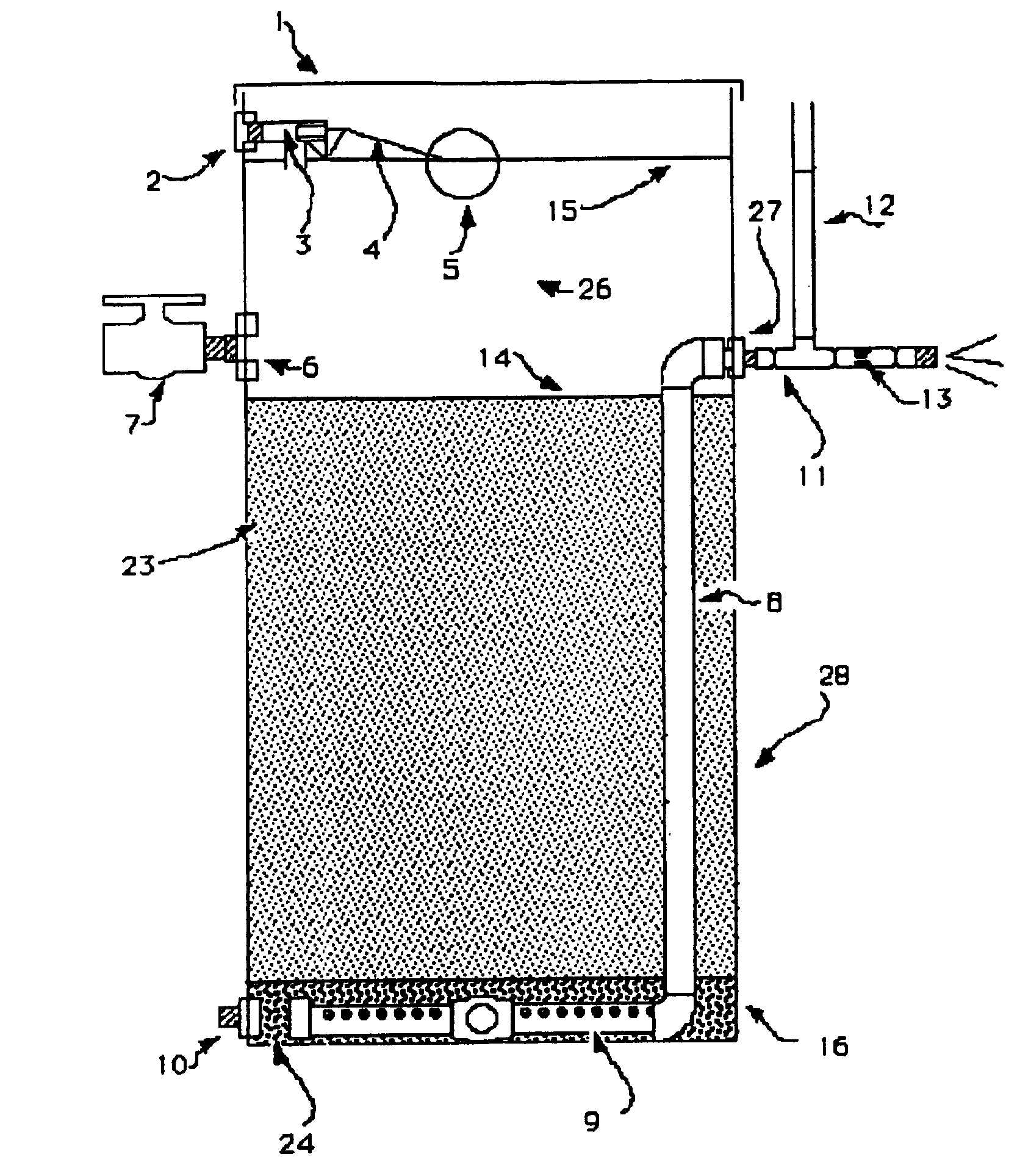
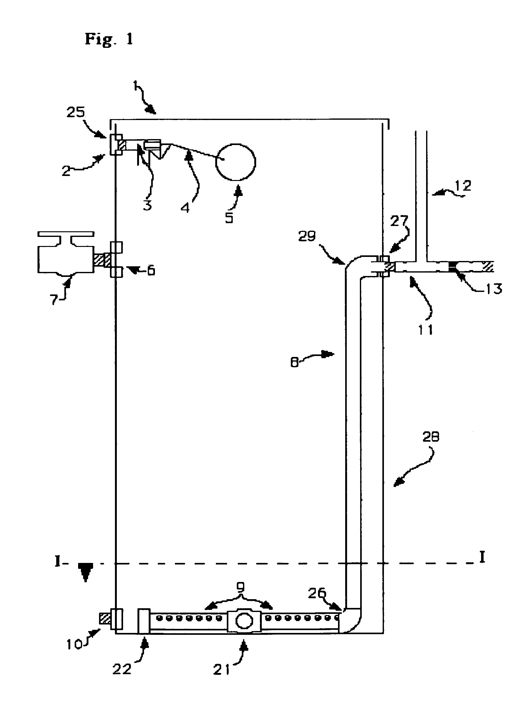
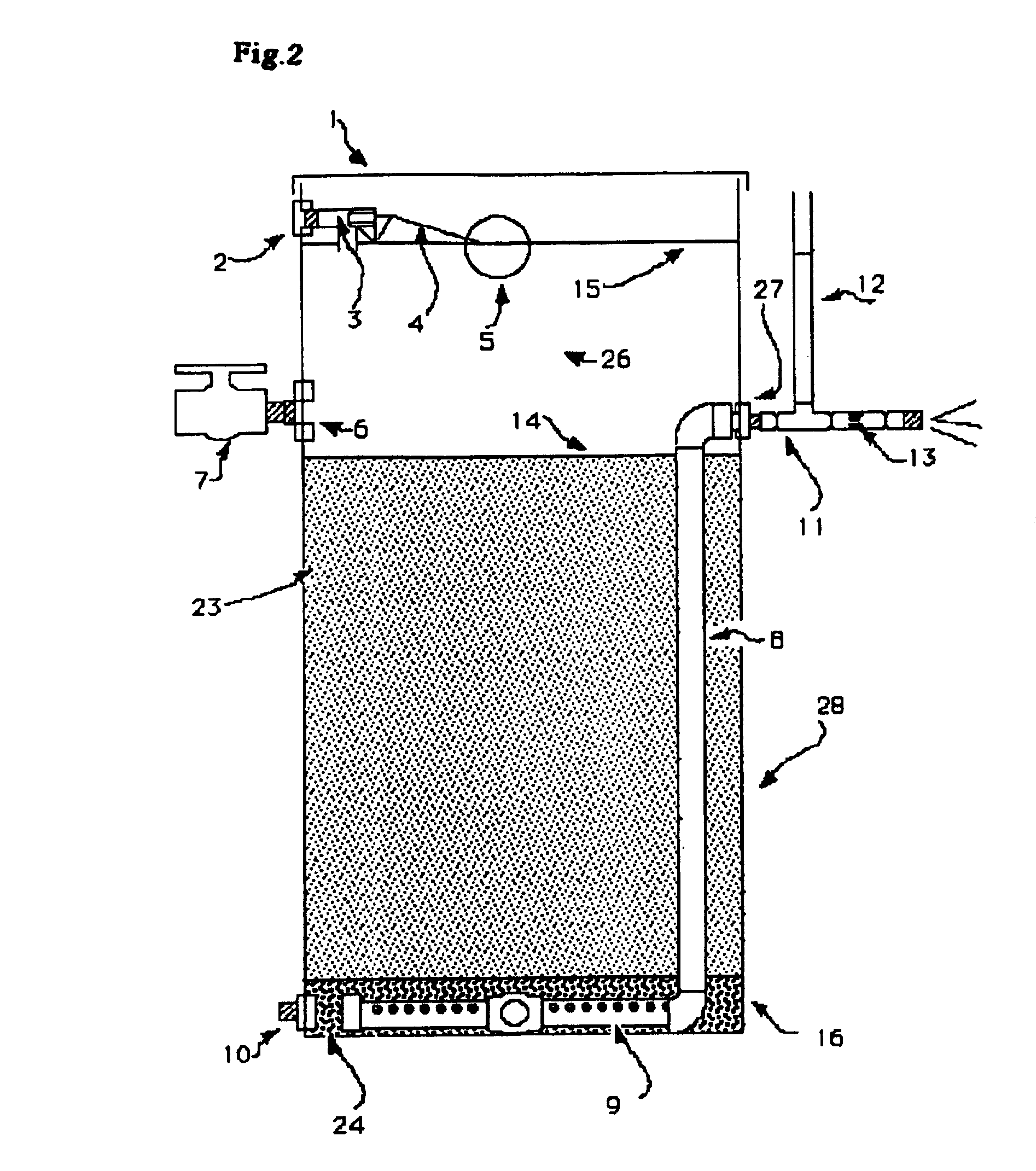
[0004]To address these issues, the inventor employed a novel piping scheme that collects water as normal at the bottom of the filter, but then proceeds through pipe work up the inside of the filter vessel exiting at a height of 36″ through a tank fitting in the vertical wall of the filter vessel. Several desirable features result from this novel piping scheme. This piping scheme prevents inappropriate piping from being installed and allows for the filter to be shipped in a more pre-assembled, self-contained condition further insuring proper installation. Placing the outlet of the filter above the filter sand level prevents the possibility of de-watering the delicate biological layer on top of the sand and thus killing it. Placing the outlet of the filter above the sand layer also provides less head pressure against the flow control device, making a larger orifice size available and thus making the flow control less susceptible to clogging. Since the piping system is pre-installed inside the filter vessel, it is not vulnerable to breakage in shipment, unpacking, or as maneuvered to install.
[0005]Secondly the inventor employed a device for flow control that attaches to the outside of the filter vessel tank fitting. This device incorporates a flow control being a neoprene washer with a precisely drilled hole that will only pass water at the rate prescribed for the filter. This eliminates guess work in installation and insures proper filter loading rate as calculated for the filter. This part of the apparatus is the only assembly on the outside of the filter. The inventor decided to place the flow control on the outside of the filter vessel so that it could be serviced without risking cross contamination possible if the flow control was located in proximity to the raw water within the filter vessel.
[0009]An unexpected result is that the internal piping scheme is safer from vandalism than exposed piping on prior art systems.

Problems solved by technology

In this regard, several problems with prior art packaged slow sand filters were noted by the inventor One problem is that most if not all package plant slow sand filters include hydraulic schemes that exit the filter at the bottom of the filter vessel and then have various piping systems that are assembled on or adjacent to the exterior of the filter (Manz U.S. Pat. No. 5,993,672, Pyper U.S. Pat. No. 5,032,261, Cluff U.S. Pat. No. 5,112,483, Simpson U.S. Pat. No. 5,264,129).
This appeared to be a problem to the inventor because it requires additional unnecessary assembly steps prior to installation.
This is a problem because there is the possibility of installing incorrect parts, loss of parts in shipment, and incorrect assembly of parts.
If the exterior pipes are installed prior to shipping, it seemed probable that they would be vulnerable to breakage in transit, unpacking, or in installation.
Placing the outlet of the filter above the filter sand level prevents the possibility of de-watering the delicate biological layer on top of the sand and thus killing it.
Another problem with prior art plants is the lack of simple headloss measurement devices.

Method used


Image

  • SSF/x slow sand filter
  • SSF/x slow sand filter
  • SSF/x slow sand filter

Examples


Embodiment Construction

[0022]It should be noted that these descriptions represent a preferred embodiment to the invention and that other possible filter vessel sizes and materials may be used without departing from the spirit and scope of the invention.

CONCLUSION

[0023]The SSF / x slow sand filter employs several features that are significant improvements over prior art. These features, such as improved internal hydraulic design, pre-calibrated maximum flow, simplified pressure head-loss monitoring, and minimal post manufacturing assembly requirements, present a filter that is significantly more trouble free and reliable to install and operate than has been available to this point.


PUM

PropertyMeasurementUnit
Lengthaaaaaaaaaa
Pressureaaaaaaaaaa

Abstract

The SSF / x slow sand filter for use in treating drinking water for homes or rural villages with features providing simpler on-site assembly, preset maximum flow, easy monitoring of pressure head loss, protection of piping, and a harrowing system for cleaning. The filter employs a novel hydraulic scheme which places most pipe and plumbing within the filter vessel. The filter employs a novel device that combines flow control, pressure measurement, freeze protection, and anti-siphon features. This in combination with a relatively shallow supernatant level provides for consistent reliable operation, easy maintenance, and reasonably long filter runs as deemed very desirable in remote rural locations.

Description

FIELD OF THE INVENTION[0001]This invention relates to the purification and filtration of drinking water.BACKGROUND AND SUMMARY[0002]Slow sand filters have been in operation for more than 150 years to provide water safe from bacteria, viruses, Giardia cysts and turbidity. Slow sand filters rely on a biologically active matrix that naturally develops on the top of the sand for high efficiency. Slow sand filters need to incorporate features that make them easy to install, and easy to maintain. Additionally slow sand filters should have features that protect the biological layer and carefully regulate flow for maximum efficiency. The advent of the use of plastic containers has resulted in a number of small packaged slow sand filters, including the current invention the SSF / x slow sand filter.[0003]It was the inventors intention to design a package slow sand filter that required as little assembly by the end-user as possible, and further embodied a complete, efficient appearance after ma...

Claims


Application Information

Patent Timeline
IPC IPC(8): B01D24/16B01D24/02
CPCB01D24/167B01D24/4861
Inventor BLACKBURN, HUMPHREY MARSHALL
Owner BLACKBURN HUMPHREY
Learn More