

Method for vaporizing a fluid using an electromagnetically responsive heating apparatus
a technology of electromagnetic responsive heating and fluid, which is applied in the direction of electric/magnetic/electromagnetic heating, lighting and heating apparatus, manufacturing tools, etc., can solve the problems of large heating element surface area, large space occupation, and inconvenient use of vapor generation methods, so as to reduce resistive electrical power loads, reduce vapor concentration levels, and high output of sterilant vapor
- Summary
- Abstract
- Description
- Claims
- Application Information
AI Technical Summary
Benefits of technology
Problems solved by technology
Method used
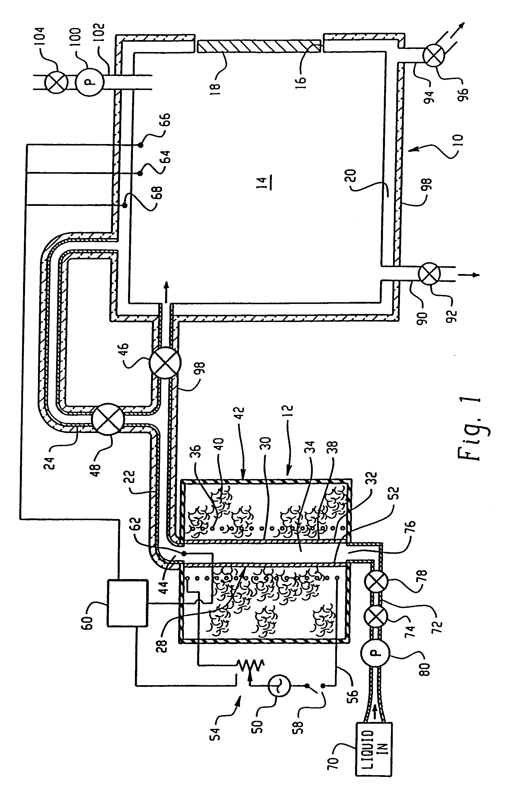
Image

Examples
example 1
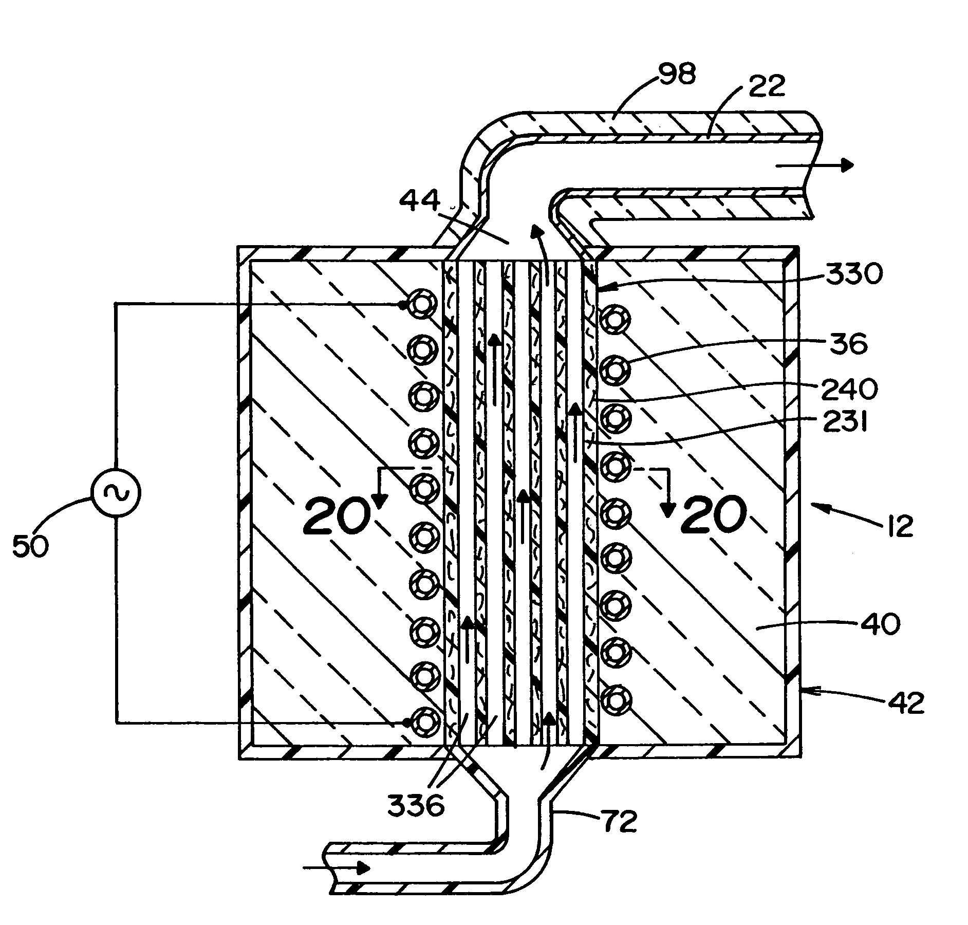
heating tube:
[0128]geometry: cylindrical[0129]wall thickness=5 mm[0130]material: resin bonded graphite[0131](skin depth)(square root of frequency)=δ√{square root over (f)}=1.592[0132]where δ is the skin depth, and f is the frequency of the electromagnetic radiation applied to the heating tube of Example 1. At a frequency of f=101.4 kHz, the applied electromagnetic radiation will have decreased to 1 / e its initial value within the wall thickness of tube 30 (i.e., 5 mm). To energize electromagnetically responsive material in the insert, electromagnetic radiation of a frequency (f1) less than 101.4 kHz should be used. In this regard, a frequency (f1) less than 101.4 kHz will result in a skin depth greater than the 5 mm wall thickness of tube 30. Accordingly, the emitted radiation has a wavelength that allows propagation through tube 30, and will impinge directly on electromagnetically responsive material in insert 180. Thus, insert 180 is heated directly by induction, rather than by con...
PUM
| Property | Measurement | Unit |
|---|---|---|
| resistance | aaaaa | aaaaa |
| pressure | aaaaa | aaaaa |
| temperature | aaaaa | aaaaa |
Abstract
Description
Claims
Application Information