Ion beam irradiation device and operating method thereof

a technology of ion beam and irradiation device, which is applied in the direction of optical radiation measurement, instruments, therapy, etc., can solve the problems of tft fracture due to static electricity, cell contamination due to particles being transferred from the rubbing cloth, and crts are problematic,

Active Publication Date: 2005-11-22
LG DISPLAY CO LTD
View PDF30 Cites 12 Cited by
  • Summary
  • Abstract
  • Description
  • Claims
  • Application Information

AI Technical Summary

Benefits of technology

[0045]Aspects of the present invention provide an ion beam irradiation device and fabrication method thereof that can perform alignment of a plurality of substrates at the same time.

Problems solved by technology

However, CRTs are problematic as they have large volumes and are heavy compared with their display areas.
However, the rubbing method is problematic for a number of reasons; since the rubbing method is performed by directly contacting the alignment layer with the rubbing cloth, cell contamination due to particles being transferred from the rubbing cloth as well as fracture of TFT due to static electricity may occur.
Further, when the rubbing method is used to produce large screens (over about 27 inches), the alignment uniformity is severely degraded, thereby reducing the production yield of the LCDs.
However, the related art ion beam irradiation device is not amenable to mass production, at least because the pretilt angle has to be reset each time the irradiated substrate is removed and a new substrate added.
This increases the time needed to form the pretilt angle, resulting in a low throughput.

Method used


Image

  • Ion beam irradiation device and operating method thereof
  • Ion beam irradiation device and operating method thereof
  • Ion beam irradiation device and operating method thereof

Examples


first embodiment

[0078

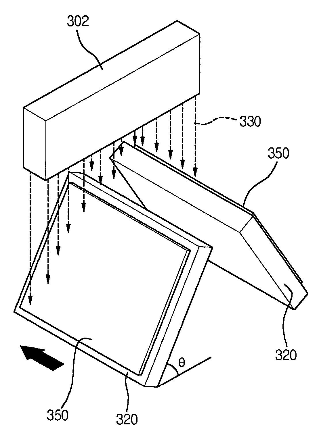
[0079]FIG. 4 is a schematic view of an ion beam irradiation device according to a first embodiment. FIG. 5 is a partial perspective view of the ion beam irradiation device of FIG. 4, and shows the alignment of the substrates.

[0080]Referring to FIGS. 4 and 5, the ion beam irradiation device 380 includes an ion beam source 300 which produces the ion beam 330, a vacuum chamber 340, a stage 310 on which the substrates 320 are mounted and valves 360 and 361. The ion beam source 300 includes a plasma forming part 301 and an ion gun 302.

[0081]The substrates 320 are coated with an alignment layer 350, mounted to the stage 310 and inclined by an angle such that a desired pretilt angle is obtained. The substrate 320 can move in one direction. The substrate 320 is irradiated by the ion beam 330 at an angle with respect to the substrate 320.

[0082]More specifically, in this embodiment, the substrates 320 are arranged parallel to the moving direction. The substrates 320 are transferred insid...

second embodiment

[0084

[0085]FIG. 6 is a schematic view of an ion beam irradiation device according to a second embodiment of the present invention. FIG. 7 is a partial perspective view of the ion beam irradiation device of FIG. 6, and shows alignment of the substrates.

[0086]The ion beam irradiation device 480 of the second embodiment is different from the ion beam irradiation device 380 of the first embodiment in that the substrates 420 are arranged differently from the substrates 320 of the first embodiment.

[0087]The ion beam irradiation device 480 includes an ion beam source 400 generating an ion beam 430 using a plasma forming part 401 and an ion gun 402, a vacuum chamber 440, a stage 410 on which the substrates 420 coated with alignment layers 450 are mounted, and valves 460 and 461.

[0088]The substrates 420 are fixed to the stage 410 and are inclined by an angle such that a desired pretilt angle is obtained. The moving substrates 420 fixed on the stage 410 are arranged perpendicular (which is he...

third embodiment

[0089

[0090]FIG. 8 is a schematic view of an ion beam irradiation device according to a third embodiment of the present invention.

[0091]The ion beam irradiation device 580 of the third embodiment is different from the ion beam irradiation devices 380 and 480 of the first and second embodiments in that the moving substrates 520 are arranged differently from the moving substrates 320 and 420 of the first and second embodiments when the ion beam is irradiated.

[0092]As shown in FIG. 8, four substrates 520 are transferred into the ion beam irradiation device 580. The four substrates 520 consist of two substrates arranged parallel to the moving direction, and two substrates arranged perpendicular to (or in series with respect to) the moving direction. Thus, the embodiment shown in FIG. 8 is similar to a combination of the previous embodiments.

[0093]The substrates 520 are arranged inclined at an angle inside the ion beam irradiation device 580 to obtain a desired alignment characteristic.

[0...


PUM

PropertyMeasurementUnit
temperatureaaaaaaaaaa
pretilt angleaaaaaaaaaa

Abstract

An ion beam irradiation device includes a vacuum chamber and a stage on which at least two substrates may be mounted such that each substrate has an inclination angle to a horizontal plane of the vacuum chamber. The stage moves in one direction. An ion gun provided in the vacuum chamber produces ion beams that irradiate the substrates. In a single pass through the vacuum chamber, the alignment layers disposed on multiple substrates may be aligned. The substrates can be aligned such that the ion beam irradiates multiple substrates simultaneously and / or such that the ion beam irradiates the multiple substrates sequentially.

Description

[0001]This application claims the benefit of priority to Korean Patent Application No. 2003-57390, filed in Korea on Aug. 19, 2003, Korean Patent Application No. 2003-57478, filed in Korea on Aug. 20, 2003, and Korean Patent Application No. 2003-57750, filed in Korea on Aug. 21, 2003, which are hereby incorporated by reference for all purposes as if fully set forth herein.BACKGROUND OF THE INVENTION[0002]1. Field of the Invention[0003]The present invention relates to an ion beam irradiation device, which irradiates an ion beam onto an alignment layer for alignment of liquid crystal molecules during fabrication of a liquid crystal display, and a method of operating the same.[0004]2. Description of the Related Art[0005]In general, cathode ray tubes (CRT) have been widely used as display devices for displaying image information on screens. However, CRTs are problematic as they have large volumes and are heavy compared with their display areas.[0006]Today, display devices are being used...

Claims


Application Information

Patent Timeline
Patent Type & Authority Patents(United States)
IPC IPC(8): G02F1/1337G02F1/13H01J37/30
CPCG02F1/133734H01J37/20H01J37/3053H01J37/317H01J2237/20207H01J2237/20221H01J2237/316
Inventor LEE, YUN BOKHAM, YONG SUNG
Owner LG DISPLAY CO LTD
Why Eureka
Try Eureka