Condensed tungsten composite material and method for manufacturing and sealing a radiation shielding enclosure

a technology of condensed tungsten and composite materials, applied in the field of radiation shielding, can solve the problems of difficult to attach lead sheets to enclosures, high cost of plate lead shielding, and x-ray radiation danger to living beings and the environmen

Inactive Publication Date: 2005-11-22
AGILENT TECH INC
View PDF8 Cites 18 Cited by
  • Summary
  • Abstract
  • Description
  • Claims
  • Application Information

AI Technical Summary

Benefits of technology

[0009]The radiation shielding enclosure may also be manufactured with a pressure spray process using condensed tungsten powder, cut fibers and an epoxy, polyester, or other suitab

Problems solved by technology

X-ray radiation is dangerous to living beings and the environment.
Plate lead shielding is very expensive and the sheets of lead are difficult to attach to an enclosure to form a shielded enclosure.
Lead is also a highly toxic material, making its use in medical, industrial and commercial settings undesirable.
It is also very difficult to se

Method used


Image

  • Condensed tungsten composite material and method for manufacturing and sealing a radiation shielding enclosure
  • Condensed tungsten composite material and method for manufacturing and sealing a radiation shielding enclosure
  • Condensed tungsten composite material and method for manufacturing and sealing a radiation shielding enclosure

Examples


first embodiment

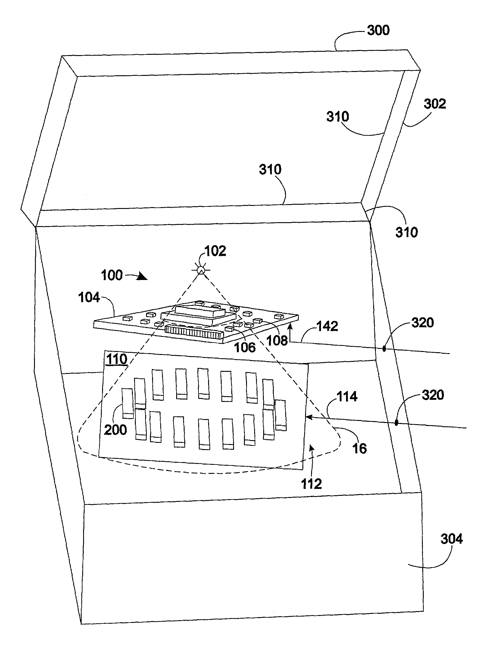
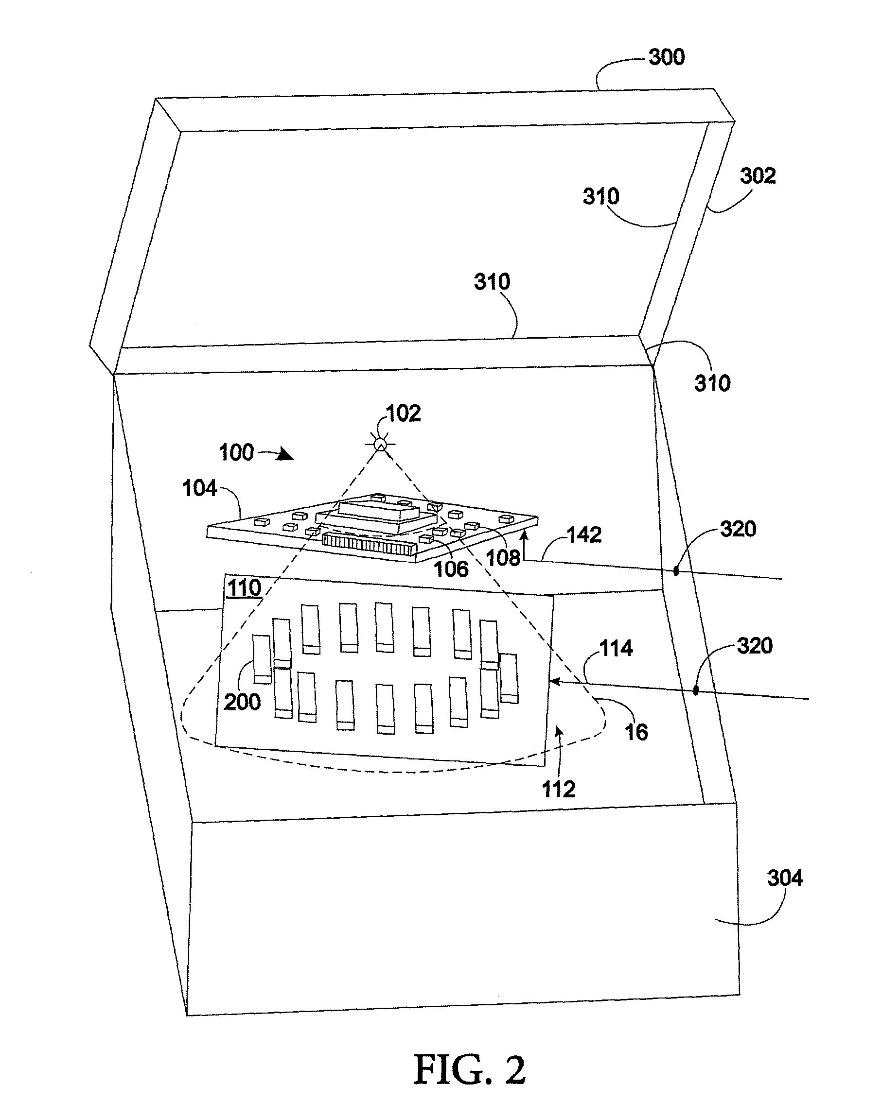
[0027]FIG. 3 shows a flow chart for a manufacturing process according to the present invention. A lay-up process 410 is used on a form to make a tungsten compound and fiber material radiation shielding enclosure. The tungsten compound may be powder tungsten and resin, polyester or epoxy substrate. The tungsten material used in the compound is a condensed form of tungsten powder. Most commercially available tungsten powders are precipitates, which do not have the high-density property of solid tungsten. Therefore the powder must be pressure and heat formed or sintered into a solid material and then returned to the powdered form by means of grinding, cutting, or a similar process. This allows the compound to use the highest possible density tungsten powder and increases the shielding ability of the compound. The tungsten compound may contain any physically similar polymerized synthetic or chemically modified natural resins including thermoplastic materials such as polyethylene and the...

second embodiment

[0031]Referring now to FIG. 5 a flow chart for a method of manufacturing a radiation shielding enclosure 300 according to the present invention. A tungsten / fiber compound is pressure sprayed 610 onto a radiation shielding enclosure mold. The tungsten / fiber compound may contain tungsten powder and cut fibers such as fiberglass in an epoxy or polyester substrate capable of pressure spraying and thermosetting or air-drying. Next, any radiation leaks are located 620 and sealed by means of tungsten caulking sealant, tungsten compound in a lay-up process or by means of tungsten / fiber pressure spraying process 630.

[0032]Installing an x-ray imaging system into the radiation shielding enclosure, routing cables through cable vias and filling voids may then be done as described above and in FIG. 4.

[0033]It will be appreciated from the above detailed description that a mesh, cloth or foil cloth of nylon, polyester, polyethylene, glass compound polyester, metal cloth, carbon fiber cloth, fibergl...


PUM


Abstract

Materials and methods of manufacturing radiation shielded enclosures is presented that may replace the use of lead, granite and other undesirable materials and manufacturing methods. The present invention provides a high-density radiation shielding enclosure manufactured using a fiberglass lay-up or pressure spaying process and tungsten powder. The method of manufacture may include applying a tungsten powder in an epoxy, caulking, sealant, adhesive or elastomeric compound to the radiation shielding enclosure in order to seal any cracks, holes, joints or other radiation leaks.

Description

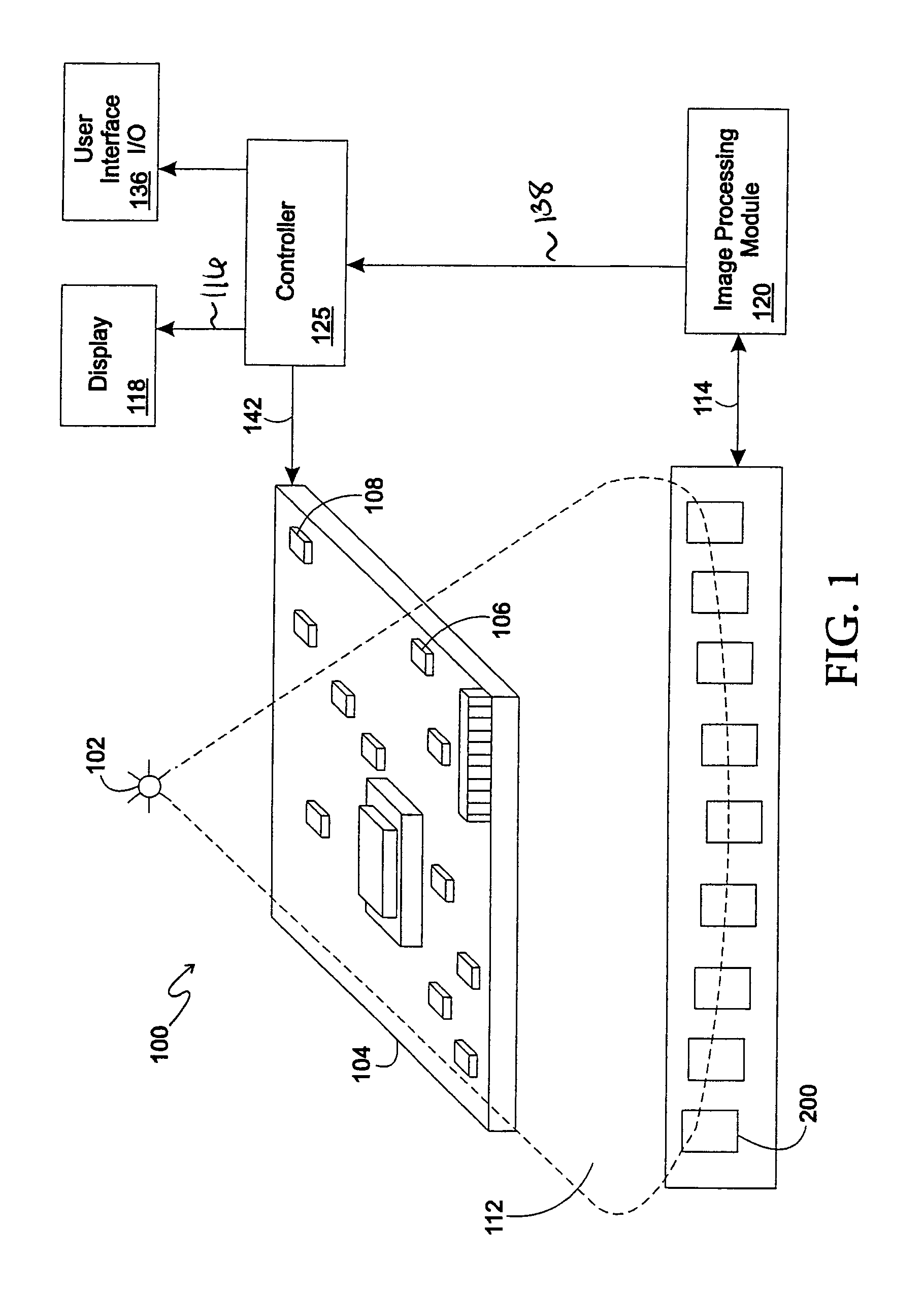
FIELD OF THE INVENTION[0001]The present invention pertains generally to the field of radiation shielding, and more particularly to materials and methods of manufacturing radiation shielding enclosures and sealing radiation leaks in radiation shielding enclosures.BACKGROUND OF THE INVENTION[0002]There are numerous uses for an x-ray shielding container, such as medical x-ray machines and industrial vision inspection machines. For example, x-ray detection is used to image dense objects, such as human bones, that are located within the body. Another application of x-ray detection and imaging is in the field of non-destructive electronic device testing. For example, x-ray imaging is used to determine the quality of solder that is used to connect electronic devices and modules to printed circuit boards.[0003]X-ray imaging works by passing electromagnetic energy at wavelengths of approximately 0.1 to 100×10−10 meters (m) through the target that is to be imaged. The x-rays are received by a...

Claims


Application Information

Patent Timeline
IPC IPC(8): G21F1/00G01N23/04G01T7/00G21F1/10G21F3/00G21K5/00
CPCG21F1/00G21Y2002/10G21Y2002/201G21Y2002/301G21Y2002/302G21Y2002/304G21Y2004/10G21Y2004/303G21Y2004/40
Inventor BATTEN, PATRICK A.SCHANK, TROY C.
Owner AGILENT TECH INC
Why Eureka
Try Eureka