Optical recorder and laser power control method

a technology of optical recorder and laser power control, which is applied in the direction of digital signal error detection/correction, instruments, recording signal processing, etc., can solve the problems of uneven recording-film, disadvantageous in cost, and technical complexity of measures, and achieve the effect of more rapid formation

Inactive Publication Date: 2005-11-22
SONY CORP
View PDF5 Cites 16 Cited by
  • Summary
  • Abstract
  • Description
  • Claims
  • Application Information

AI Technical Summary

Benefits of technology

[0014]Under the above situation, an object of the present invention is to allow a recording operation to be always executed at the most appropriate laser power to obtain a high-quality reproduced signal.
[0021]Pit marks are formed more quickly with respect to laser emission on recording media having organic pigment films than on, for example, recording media having general phase-change recording films. In other words, an effect of the pit mark being recorded by the current laser illumination appears on reflected light obtained by the laser illumination. “Pit marks are formed more quickly,” described above, means that pit marks are generated so “quickly” that the pit mark being recorded changes the quantity of reflected light of the recording laser.

Problems solved by technology

On the disk, recording-film unevenness may occur from the center to the peripheral of the disk due to a recording-film forming process in manufacturing the recording medium.
With these points being taken into consideration, the most appropriate laser power obtained by power calibration performed at the test-writing area on the disk at a point of time is not necessarily the most appropriate recording laser power for the entire area of the disk or under every environmental condition, which includes temperature changes.
These measures are, however, technically complicated and disadvantageous in terms of cost.

Method used


Image

  • Optical recorder and laser power control method
  • Optical recorder and laser power control method
  • Optical recorder and laser power control method

Examples


example 1

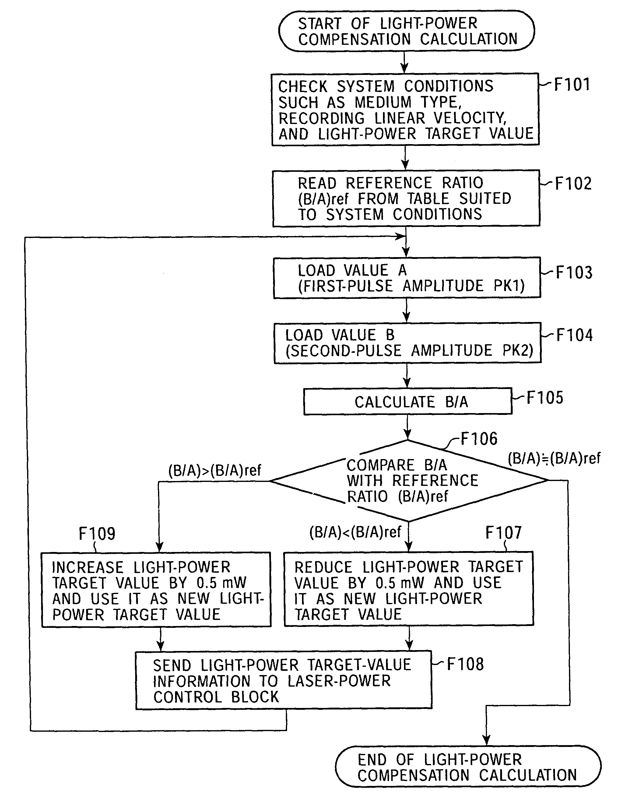
[0197]A specific example of the laser-power compensation processing performed in the system controller 10, that is, the processing executed by the functional blocks shown in FIG. 9 inside the system controller 10, will be described by referring to FIG. 11.

[0198]Steps shown in FIG. 11 correspond to the functional blocks shown in FIG. 9 as follows:

[0199]F101 and F102: Compensation-reference holding section 10d

[0200]F103 and F104: Sampled-value input section 10a

[0201]F105: Estimation calculation section 10b

[0202]F106 to F109: Compensation calculation section 10c

[0203]In the recording-laser-power compensation processing, the system controller 10 first checks various system conditions related to a recording operation in step F101. More specifically, the system controller 10 checks a medium type, a recording linear velocity, and a recording-power target value.

[0204]Then, in step F102, a reference ratio (B / A)ref suited to the system conditions is read from the data table stored in the ...

example 2

[0220]FIG. 12 shows a processing example which can be employed in stead of that shown in FIG. 11, as recording-power compensation processing.

[0221]Since steps F201 to F205 are the same as steps F101 to F105 shown in FIG. 11, a description thereof is omitted.

[0222]In the processing example shown in FIG. 12, after the ratio B / A is calculated in step F205, (B / A) / (B / A)ref is calculated in step F206.

[0223]Then, in step F207, it is determined whether (B / A) / (B / A)ref is “1” or not. When it is not “1” (does not fall in a area where it is regarded as “1”), the processing proceeds to step F208.

[0224]In F208, a ratio α corresponding to the shift of the ratio B / A against the reference ratio (B / A)ref is calculated.

[0225]FIG. 13 shows the relationship between the recording power, and the ratio B / A and the reference ratio (B / A)ref obtained from the table data. Under the current system conditions, it is assumed that recording power Pref shown in the figure is the most appropriate. In this case, acco...


PUM

PropertyMeasurementUnit
poweraaaaaaaaaa
wavelengthaaaaaaaaaa

Abstract

An optical recording apparatus obtains the most appropriate recording laser power state in real time according to an environmental mark-generation condition. When data is recorded (mark is generated) by emitting pulse-train-manner laser outputs to an organic-pigment recording medium, a first signal value corresponding to a first pulse in the pulse-train-manner laser outputs and a second signal value corresponding to second and subsequent pulses in the pulse-train-manner laser outputs are detected as a reflected-light information signal; the ratio thereof is obtained; and the obtained ratio and a reference ratio are used to generate a laser-power compensation signal to control the power of the laser outputs.

Description

TECHNICAL FIELD[0001]The present invention relates to optical recording apparatuses for recording into recording media such as optical disks, and laser-power control methods.BACKGROUND ART[0002]CD-type and DVD-type optical disks have been widely known as optical recording media. Especially as write-once media and rewritable media, media for which data recording can be performed at a user side, and recording apparatuses have also been spread.[0003]For example, CD-Rs (compact discs recordable) and DVD-Rs (digiral versatile discs recordable) are typically used as write-once media. In the disks, organic pigment films are used as disk recording layers, and pits (marks) are formed by organic-pigment changes when a laser is emitted to data tracks formed as pre-grooves.[0004]When data is recorded in such recording media, if laser power is optimized, pits are successfully formed and therefore, the quality of a reproduced signal is improved when reproduction.[0005]To this end, when an organic...

Claims


Application Information

Patent Timeline
Patent Type & Authority Patents(United States)
IPC IPC(8): G11B7/0045G11B7/125G11B7/004G11B7/00G11B7/1263
CPCG11B7/00456G11B7/1263G11B7/1267G11B7/00458G11B7/0045
Inventor UDAGAWA, TOSHIKINISHIURA, TARO
Owner SONY CORP
Why Eureka
Try Eureka