Exhaust apparatus for vehicle

a technology for exhaust apparatus and vehicle, which is applied in the direction of filtration separation, auxillary pretreatment, separation process, etc., can solve the problems of unwoid and complicated structure of spark arrester, and achieve the effect of simple structure and augmented sound reduction performan

Inactive Publication Date: 2005-11-29
HONDA MOTOR CO LTD
View PDF25 Cites 39 Cited by
  • Summary
  • Abstract
  • Description
  • Claims
  • Application Information

AI Technical Summary

Benefits of technology

[0009]The present invention has been made in view of such a circumstance as described above. It is an object of the present invention to provide an exhaust apparatus for a vehicle wherein, while a spark arrester body is kept in a simple structure, expansion and contraction of exhaust gas are carried out in the spark arrester to augment the sound reduction performance.
[0011]With such a configuration as described above, only if the tail pipe on which the annular partition plate is securely mounted is inserted into the spark arrester body, a plurality of expansion rooms and a throttle path which communicates the expansion rooms with each other are formed between the tail pipe and the spark arrester body. Thus, when exhaust gas circulates between adjacent expansion rooms through the throttle path, expansion and contraction of exhaust gas is carried out also in the spark arrester. Consequently, the sound reduction performance can be augmented. In addition, the spark arrester body can be kept in a simple structure only by securely mounting the annular partition plate on the tail pipe.
[0012]According to the present invention, the exhaust apparatus for a vehicle includes a tail pipe that is removably mounted on the spark arrester. According to such a configuration as just described, alteration of the muffler characteristic by replacement of the tail pipe is facilitated.

Problems solved by technology

In this instance, however, if a partition plate is provided in the spark arrester, then the structure of the spark arrester is complicated, which is not desirable.

Method used


Image

  • Exhaust apparatus for vehicle
  • Exhaust apparatus for vehicle
  • Exhaust apparatus for vehicle

Examples


first embodiment

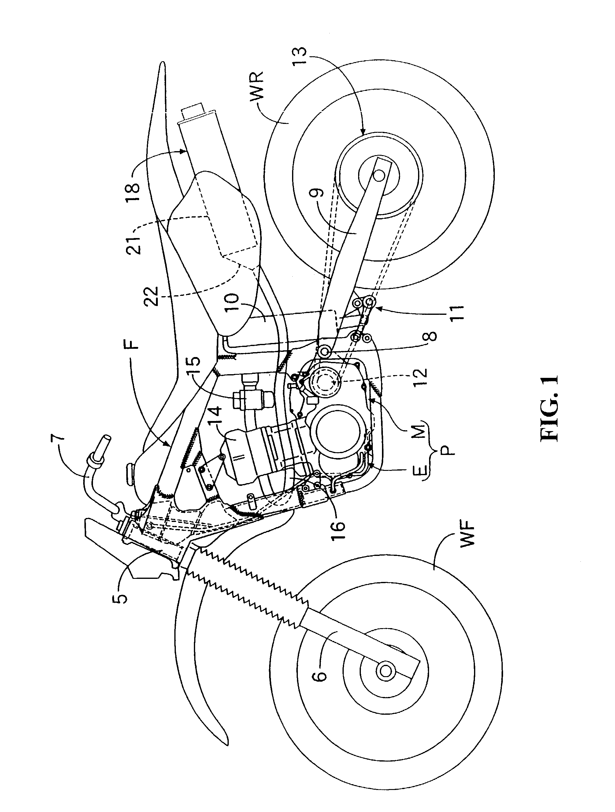
[0022]FIGS. 1 to 5 show the present invention. Referring first to FIG. 1, a front fork 6 for supporting a front wheel WF for rotation thereon is supported for steering operation on a head pipe 5 provided at a front end of a body frame F of the motorcycle, and a steering handle bar 7 is connected to the front fork 6. Meanwhile, a rear fork 9 is supported at a front portion thereof for upward and downward rocking motion on the body frame F through a support shaft 8, and a rear wheel WR is supported for rotation at a rear portion of the rear fork 9.

[0023]A rear cushion unit 10 is connected at an upper portion thereof to an upper portion of the body frame F, and the rear cushion unit 10 is connected at a lower portion thereof to an intermediate portion of the rear fork 9 through a link mechanism 11.

[0024]A power unit P including an engine E and a transmission M is carried on the body frame F, and power outputted from the power unit P, that is, power outputted from an output power shaft ...

second embodiment

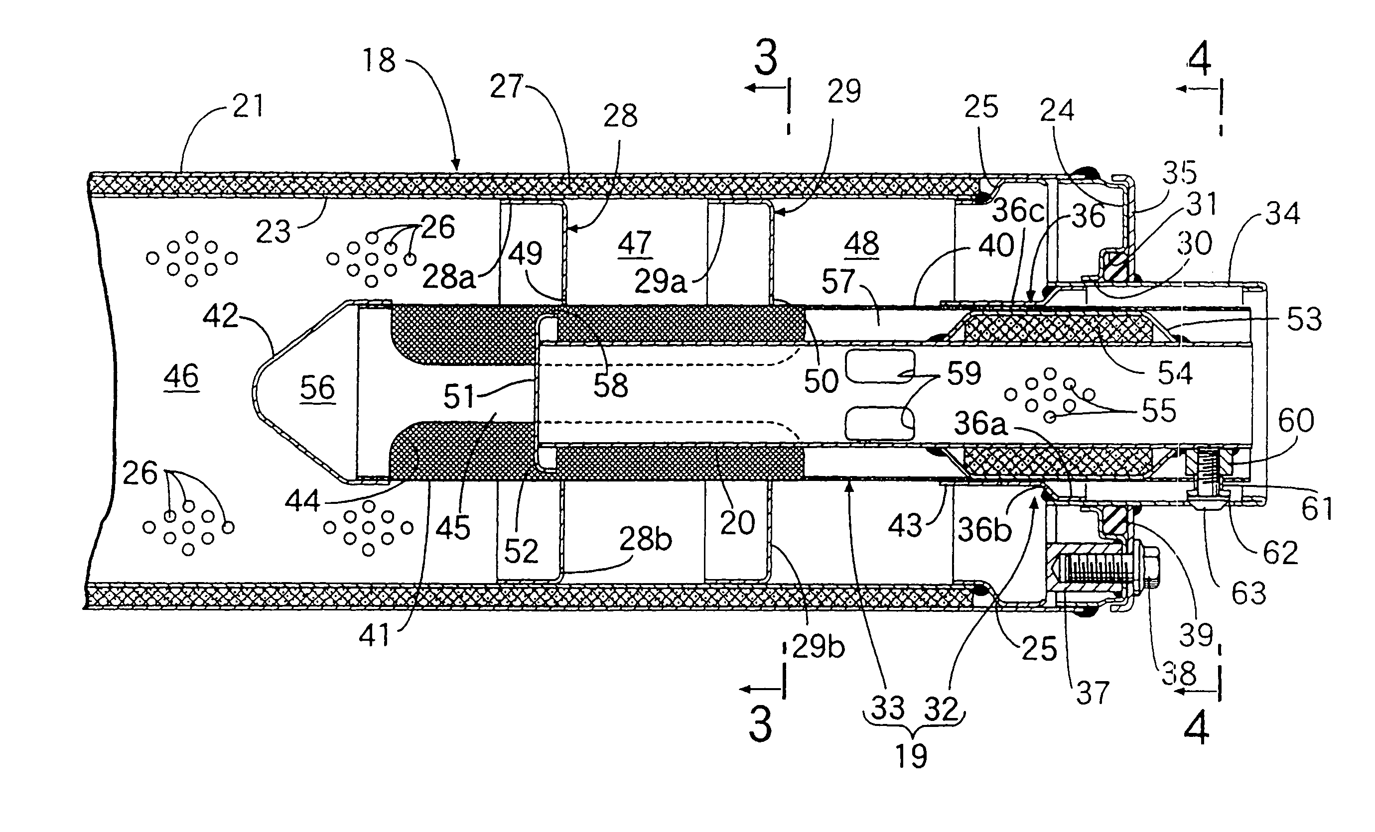
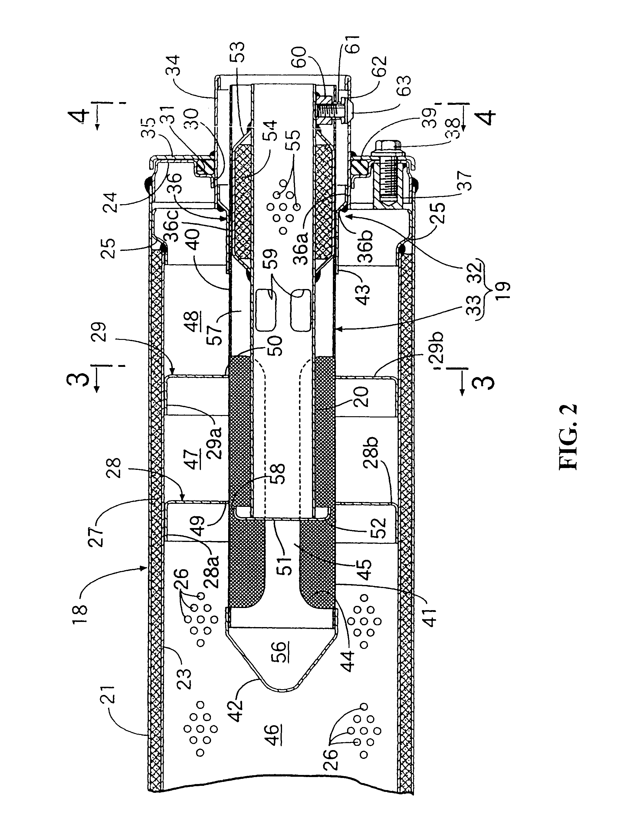
[0054] expansion and contraction of exhaust gas is repeated a greater number of times in the spark arrester body 33, and the sound reduction performance can be further augmented. In addition, in order to form the fourth, sixth and seventh expansion chambers 56, 66, 67 and the third and fourth throttle paths 58, 68 interconnecting the expansion chambers 56, 66, 67 in the spark arrester body 33, it is only necessary to insert the tail pipe 20 having the annular partition plates 52, 65 securely mounted thereon into the spark arrester body 33. Thus, the spark arrester body 33 can be maintained in a simple structure.

[0055]While embodiments of the present invention are described above, the present invention is not limited to the embodiments described above but allows various design modifications without departing from the present invention.

[0056]As described above, only when the tail pipe on which the annular partition plate is securely mounted is inserted into the spark arrester body doe...


PUM

PropertyMeasurementUnit
distanceaaaaaaaaaa
sound reduction performanceaaaaaaaaaa
cylindrical shapeaaaaaaaaaa

Abstract

An exhaust apparatus for a vehicle includes a spark arrester having a tubular spark arrester body assembled on a rear portion of a muffler connected to an exhaust pipe. A tail pipe is inserted in the spark arrester body and is mounted on the spark arrester such that exhaust gas flowing through the muffler is discharged into the atmospheric air from the tail pipe through the spark arrester, to carry out, expansion and contraction of exhaust gas in the spark arrester occurs to augment the sound reduction performance. An annular partition plate cooperates with an inner face of a spark arrester body to form a throttle path therebetween that is securely mounted on a tail pipe wherein a plurality of expansion chambers that communicate with each other through the throttle path are formed between the tail pipe and the spark arrester body with the annular partition plate disposed therebetween.

Description

CROSS-REFERENCE TO RELATED APPLICATIONS[0001]The present nonprovisional application claims priority under 35 USC 119 to Japanese Patent Application Number 2001-385989 filed on Dec. 19, 2001 the entire contents thereof is hereby incorporated by reference.BACKGROUND OF THE INVENTION[0002]1. Field to Which the Invention Pertains[0003]This invention relates to an exhaust apparatus for a vehicle wherein a spark arrester having a tubular spark arrester body is assembled to a rear portion in a muffler connected to an exhaust pipe and a tail pipe inserted in the spark arrester body is mounted on the spark arrester such that exhaust gas flowing through the muffler is discharged into the atmospheric air from the tail pipe through the spark arrester.[0004]2. Description of Background Art[0005]Conventionally, an apparatus as described above is disclosed, for example, in the official gazette of Japanese Patent Laid-Open Number Hei 8-61046, the official gazette of Japanese Patent Laid-Open Number...

Claims


Application Information

Patent Timeline
Patent Type & Authority Patents(United States)
IPC IPC(8): F01N1/08F01N1/10F01N1/24F01N3/06F01N13/08F01N13/18
CPCF01N1/083F01N1/10F01N1/24F01N3/06F01N13/08F01N13/18F01N13/1855F01N2450/24F01N2590/04Y10S55/20Y10S55/30
Inventor KAWAMATA, NORIYUKIKOISHI, HIROAKIKURATA, KOU
Owner HONDA MOTOR CO LTD
Why Eureka
Try Eureka