Power switching apparatus

a power switching and electronic control technology, applied in the direction of ac network voltage adjustment, information technology support system, climate sustainability, etc., can solve the problems of premature wear-out or even failure of relays, electronic controlled power switching apparatus with a large operating current range from being used in practical applications, and inconvenient to cater for extra power supply lines, etc., to achieve wide current rating range, large current rating range, and reasonable compact size

Inactive Publication Date: 2005-11-29
CLIPSAL ASIA HLDG
View PDF3 Cites 37 Cited by
  • Summary
  • Abstract
  • Description
  • Claims
  • Application Information

AI Technical Summary

Benefits of technology

[0009]Accordingly, it is an object of the present invention to provide electronic controlled power switching apparatus with line-powered switching controlled circuitry having a wider current rating range while maintaining a reasonably compact size. It is also an object of this invention to provide a line-powered controlled switching apparatus of a compact design using electronic controlled relays as the power switching elements of a power rating comparable to that of the steady “ON-” state operating state conditions. At a minimum, it is an object of this invention to provide the public with a useful choice of electronic controlled power switching apparatus. More s

Problems solved by technology

In many power distribution wiring networks, for example, networks at home or offices, extra power supply lines are not readily available to cater for the operating power requirements of an electronic controlled power switching apparatus.
This dual requirement has been a major obstacle preventing electronic controlled power switching apparatus with a large operating current range from being used in practical applications, especially in applications in which a compact design is desired.
Hence, it is not surprising that electronic controlled power switching apparatus ada

Method used


Image

  • Power switching apparatus
  • Power switching apparatus
  • Power switching apparatus

Examples


specific example

[0082]In a specific example of a switching apparatus with the topology of FIGS. 5 and 5a for fitting into a 35 mm wall socket conforming to British standard BS4662, with the number of gangs or channels n=4 and with a load rating range of between 15 to 1600 VA, the following are the exemplary components and their descriptions.

[0083]The electromechanical switching device is an Omron G6S relay with a Rated Carry Current of 2 A which means the maximum recommended switching current should not exceed 2 A. For application in a switching Voltage=250, the normal maximum switching current (without protection) would be under 0.26 A so as not to exceed the maximum switching current. The electronic controllable shunting means is a triac of the ST T4 series which is specified for a current flow between 0.06 and 0.75 A. As an example, when the current flowing through the triac is approaching or at 0.75 A, the relay will be switched on so as to shift current passage from the triac to the relay. The...


PUM


Abstract

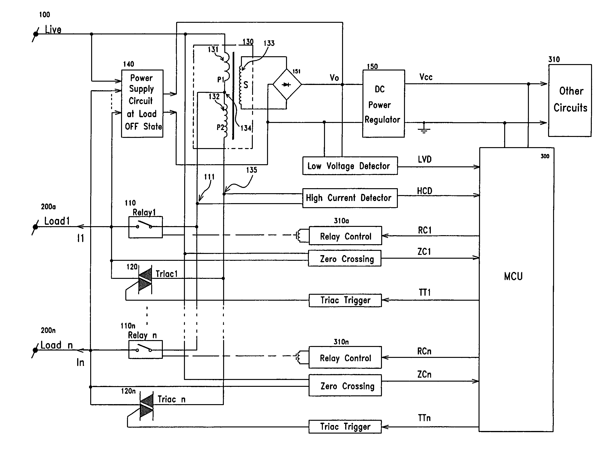
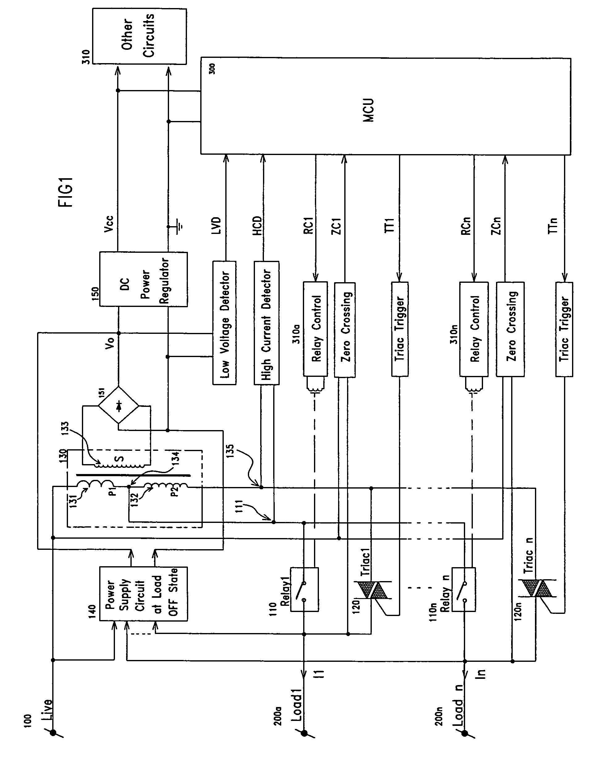
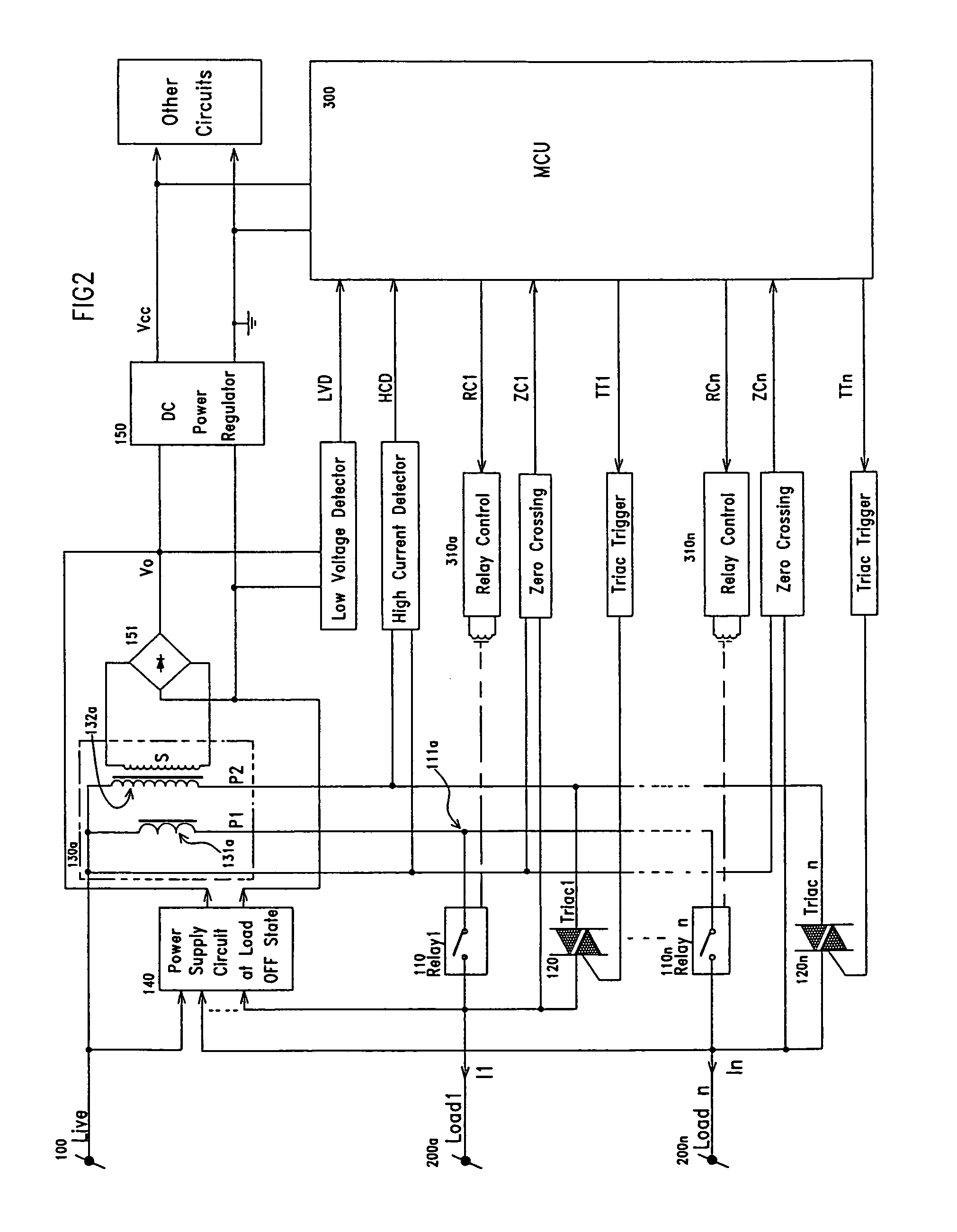
A power switching apparatus comprising a current transformer with coupled primary and secondary windings, the primary windings being adapted for series connection between alternate current power source and load, the primary windings comprising first and second sub-primary windings of different number of turns of windings and respectively of a larger and a smaller core diameter, a current conduction path being provided from intermediate the first and the second sub-primary windings to the power switching means so that upon detection of a current exceeding the current rating of the second sub-primary windings, current will be caused to flow from alternate current power source to load via a current loop comprising the power switching means and the first sub-primary windings only.

Description

FIELD OF THE INVENTION[0001]The present invention relates to electronic controlled power switching apparatus and, more particularly, to line-powered electronic controlled power switching apparatus. More specifically, although of course not solely limited thereto, this invention relates to line-powered electronic controlled power switching apparatus for use in a two-wire system. This invention also relates to multi-gang line-powered electronic controlled power switching apparatus with a relay adapted for a high current handling capability and relay protection means.BACKGROUND OF THE INVENTION[0002]Electronic controlled power switching apparatus provide useful alternative to conventional rocker-type switches so that power switching, for example, switching of electrical appliances and lighting apparatus, can be done by remote or wireless controlled switching, non-contact switching, touch switching or other intelligent or more sophisticated switching methods.[0003]Electronic controlled ...

Claims


Application Information

Patent Timeline
IPC IPC(8): H02J1/00H02J3/14H02J13/00
CPCH02J3/14H02J13/0006Y04S20/222Y02B70/3225H02J13/00002Y04S10/30Y02E60/00
Inventor LEE, KWOK KIT PATRICK
Owner CLIPSAL ASIA HLDG
Why Eureka
Try Eureka