Fluid density measurement in pipes using acoustic pressures

Inactive Publication Date: 2005-12-06
WEATHERFORD TECH HLDG LLC
View PDF114 Cites 68 Cited by
  • Summary
  • Abstract
  • Description
  • Claims
  • Application Information

AI Technical Summary

Benefits of technology

[0012]The present invention allows the density to be determined in a pipe independent of pipe orientation, i.e., vertical, horizontal, or any orientation therebetween. Also, the invention does not require any disruption to the flow within the pipe (e.g., an orifice or venturi). Furthermore, if fiber optic sound speed meters are used to obtain the effective sound speed measurements, which are well suited to the harsh down hole environment, such meters eliminate the need for any electronic components down ho

Problems solved by technology

However, such techniques require precise control of the acoustic source and are costly and/or complex to implement via electronics.
Such reflection and scattering inhibit the ability of the instrument to determine the propagation velocity.
For this reason, the application of ultrasonic flow meters has been limited pri

Method used


Image

  • Fluid density measurement in pipes using acoustic pressures
  • Fluid density measurement in pipes using acoustic pressures
  • Fluid density measurement in pipes using acoustic pressures

Examples


Example

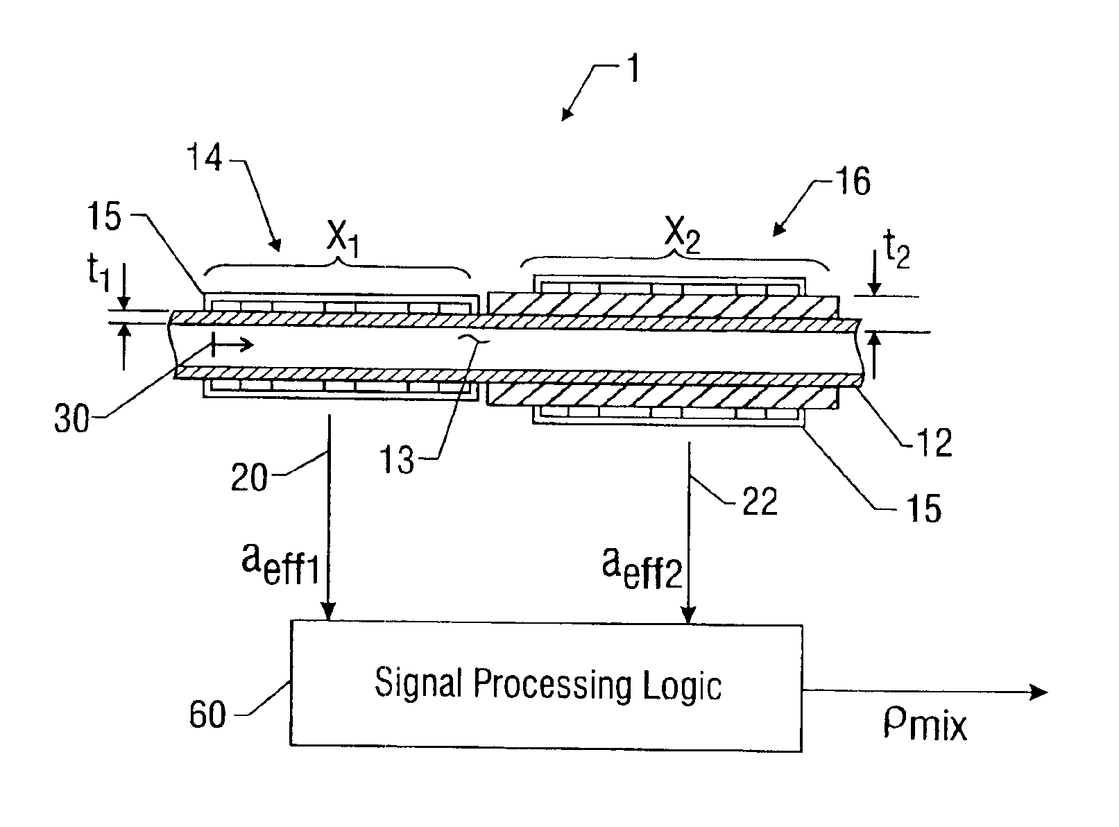
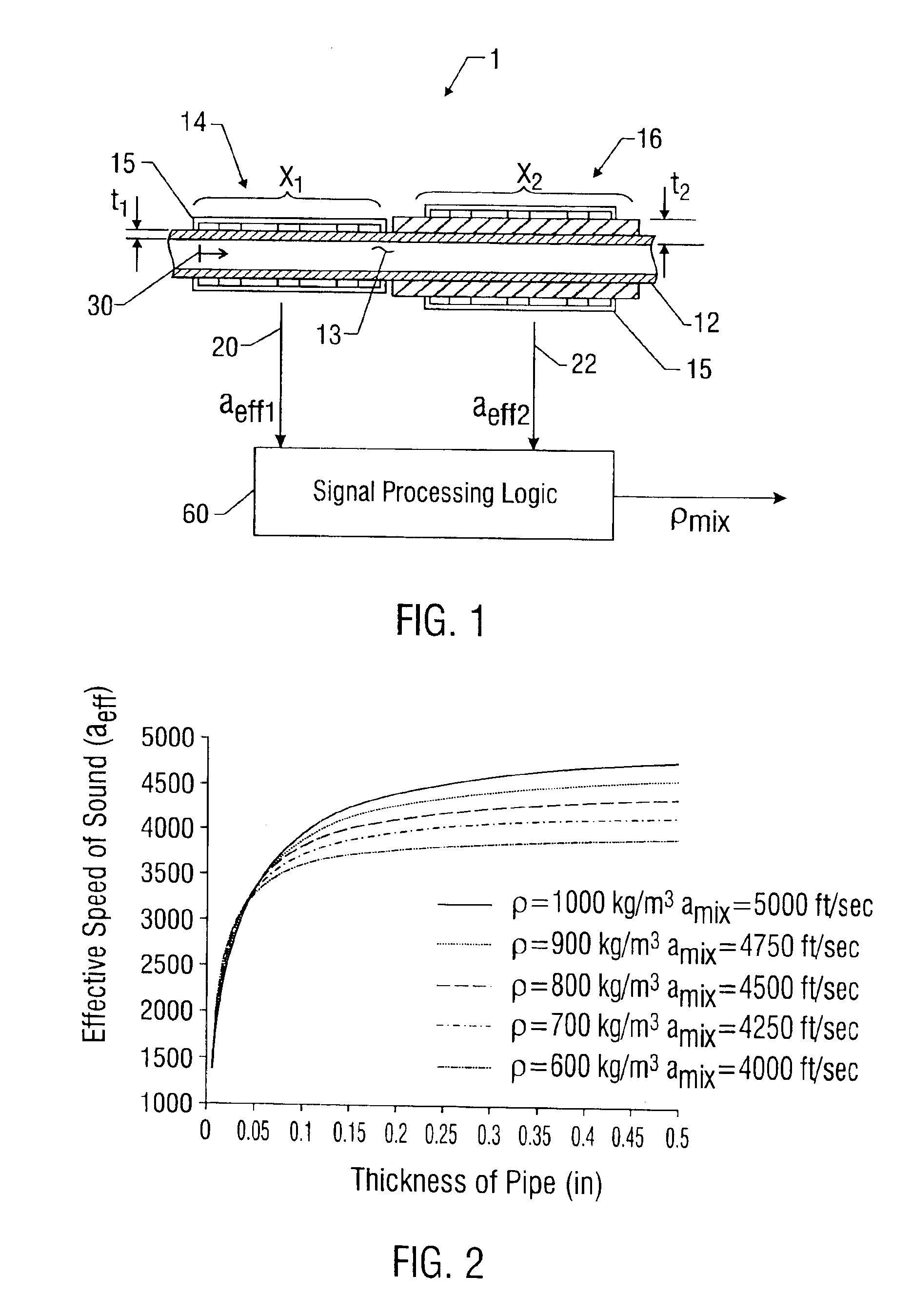
[0024]The density meter 1 of FIG. 1 uses a pair of sound speed meters 14, 16 placed at axial locations, or sensing regions, X1, X2 along the pipe 12 for measuring the density of at least one fluid in a pipe 12. The sound speed meters 14, 16 provide the effective speed of sound a1eff and a2eff of the fluid / pipe system on lines 20, 22 which are provided to signal processing logic αwhich determines the density of the fluid (or mixture) in the pipe 12 using relationships between the compliance of the pipe and various fluid parameters as will be more fully described below. Numerous sensing and processing techniques may be employed to further determine the infinite speed of sound amix∞ of the fluid in the fluid / pipe system from the measured effective speed of sound aeff, such as those disclosed in U.S. patent application Ser. No. 09 / 344,094, entitled “Fluid Parameter Measurement in Pipes Using Acoustic Pressures,” filed Jun. 25, 1999, the disclosure of which is incorporated herein by refe...


PUM


Abstract

The density of at least one fluid in a pipe is determined using a pair of effective sound speeds a1eff and a2eff of the fluid/pipe system. The pair of effective sound speed measurements is taken at two sensing regions along the pipe wherein each of the sensing regions has a different cross sectional area compliance. The pair of effective sound speeds a1eff and a2eff is provided to signal processing logic 60, which determines the density of the fluid flowing in the pipe. The effective sound speeds a1eff and a2eff may be provided by a pair of sound speed meters positioned at the sensing regions wherein the sound speed meters utilize a spatial array of acoustic pressure sensors placed at predetermined axial locations along the pipe. The acoustic pressure sensors measure one-dimensional planar acoustic waves that are lower in frequency (and longer wavelength) signals than those used for ultrasonic flow meters, and thus is more tolerant to inhomogeneities in the flow. In addition, no external acoustic source is required and the meters may operate using passive listening.

Description

CROSS REFERENCES TO RELATED APPLICATIONS[0001]This application contains subject matter related to that disclosed in U.S. patent applications Ser. No. 09 / 344,094, entitled “Fluid Parameter Measurement in Pipes Using Acoustic Pressures,” filed Jun. 25, 1999; Ser. No. 09 / 344,070, entitled “Measurement of Propagating Acoustic Waves in Compliant Pipes,” filed Jun. 25, 1999; Ser. No. 09 / 344,069, entitled “Displacement Based Pressure Sensor Measuring Unsteady Pressure in a Pipe,” filed Jun. 25, 1999; and Ser. No. 09 / 344,093, entitled “Non-Intrusive Fiber Optic Pressure Sensor for Measuring Unsteady Pressures within a Pipe,” filed Jun. 25, 1999, all of which are incorporated herein by reference.TECHNICAL FIELD[0002]This invention relates to fluid parameter measurement in pipes and more particularly to measuring speed of sound and density of fluids in pipes using acoustic pressures. The measurement exploits the interaction between pipe flexibility, speed of sound propagation, and density of ...

Claims


Application Information

Patent Timeline
IPC IPC(8): G01N9/00G01N9/24G01N29/024
CPCG01N9/002G01N9/24G01N29/024G01N2009/006G01N2291/0212G01N2291/0217G01N2291/02818G01N2291/02836G01N2291/02872G01N2291/0421G01N2291/105
Inventor GYSLING, DANIEL L.
Owner WEATHERFORD TECH HLDG LLC
Why Eureka
Try Eureka