Super low NOx, high efficiency, compact firetube boiler

a firetube boiler, high efficiency technology, applied in the direction of fire-tube steam boilers, machines/engines, lighting and heating apparatus, etc., can solve the problems of inability to teach nor suggest the possibility of reducing nosub>, high cost and complexity of combustion process and firetube boilers, etc., to achieve the effect of reducing nox emissions

Active Publication Date: 2005-12-06
GAS TECH INST
View PDF9 Cites 23 Cited by
  • Summary
  • Abstract
  • Description
  • Claims
  • Application Information

AI Technical Summary

Benefits of technology

[0012]It is another object of this invention to provide a firetube boiler capable of reducing NOx emissions below the level of conventional firetube boilers, down to the super-low level of 5 ppmv at 3% O2.

Problems solved by technology

However, this patent neither teaches nor suggests the possibility of reducing NOx emissions to the currently desired level of less than about 5 ppmv corrected to 3% O2.
However, extracting heat from the combustion process by a heat absorbing surface inserted into the apparatus and transporting it away from the apparatus as taught by this patent represents an impractical concept, especially in the firetube boiler technology which employs natural water circulation in two inside and outside pressurized vessels.
Insertion of a forced circulation heat transfer coil into the first stage combustion chamber makes the combustion process and firetube boiler more expensive and complicated, including an addition of electrical consumption for pumping water through the coil.
Heretofore it has been thought to be impractical to utilize staged combustion in a firetube boiler because there is no known way for introducing a secondary stream of oxidant through the pressurized boiler shell into the furnace.
Thus, until now, the reduction of NOx emissions from firetube boilers to the desired super-low level of 5 ppmv at 3% O2 has not been readily achievable.

Method used


Image

  • Super low NOx, high efficiency, compact firetube boiler
  • Super low NOx, high efficiency, compact firetube boiler
  • Super low NOx, high efficiency, compact firetube boiler

Examples


Embodiment Construction

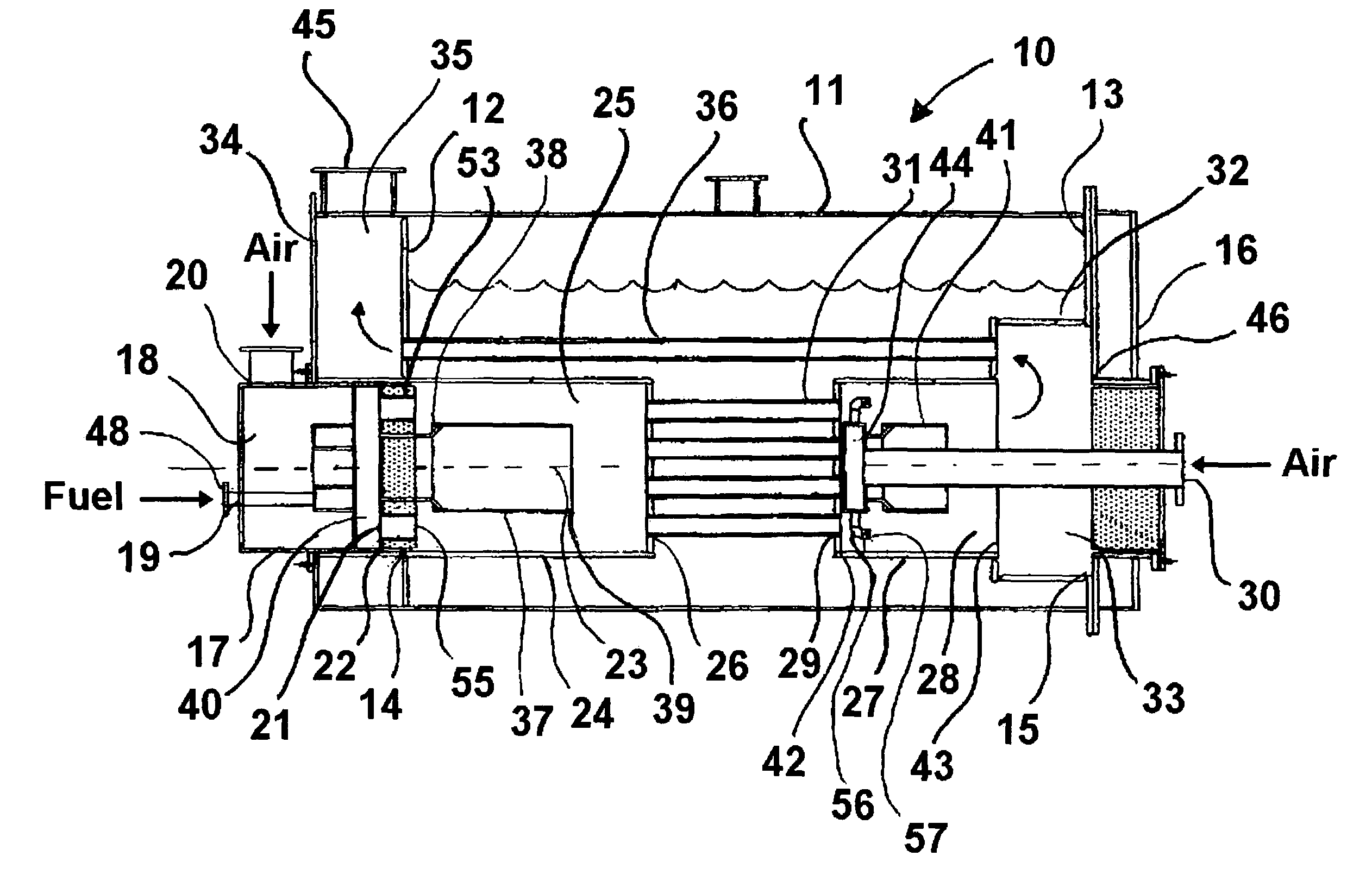
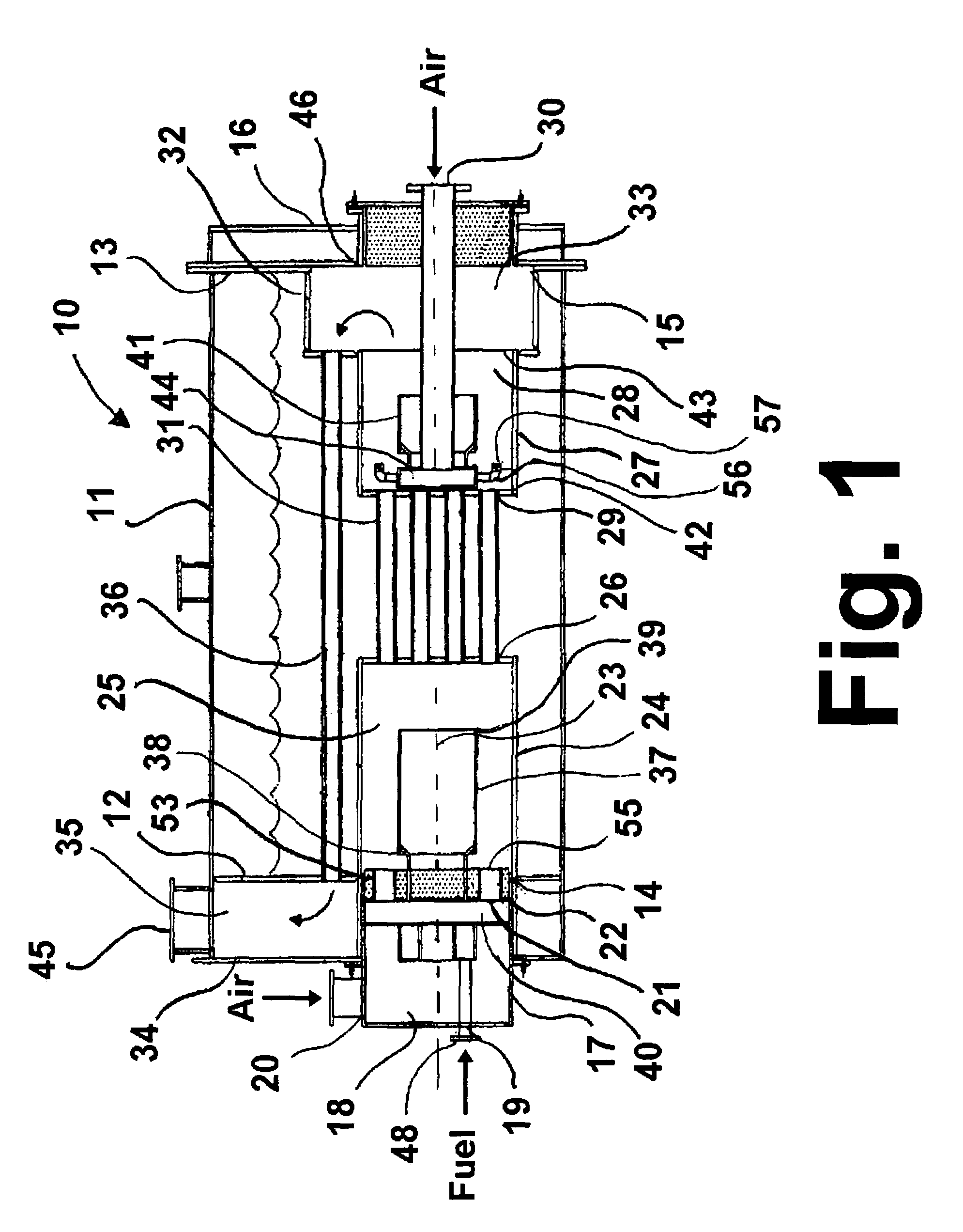
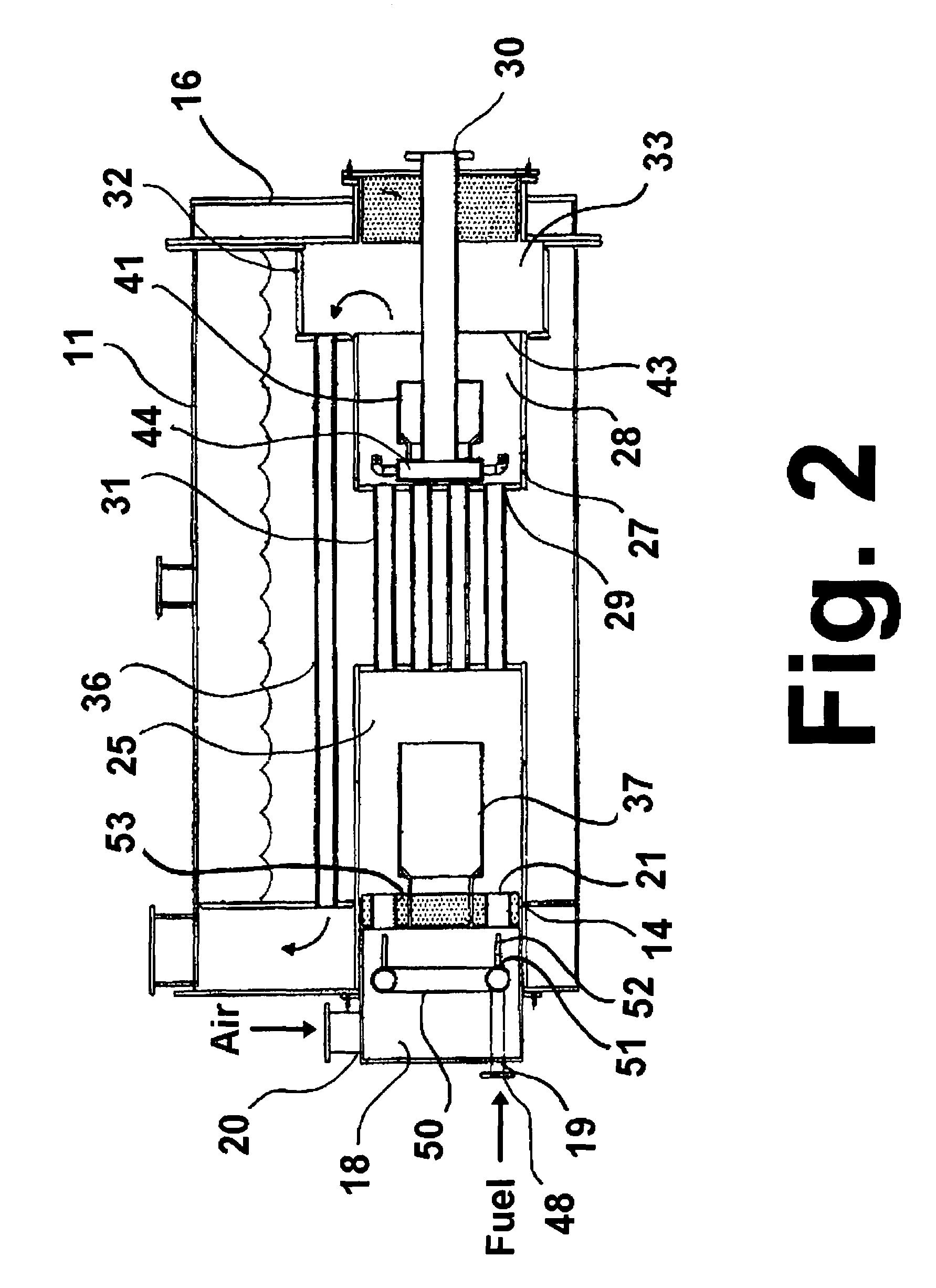
[0023]In general terms, the invention claimed herein comprises a firetube boiler having a first pass furnace that is divided into a primary combustion chamber, in-line integral tubular heat transfer section, and a secondary combustion chamber. The in-line integral tubular heat transfer section is constructed of conventional tube sheets with axial firetubes having designs which include dimpled tubes, integral finned tubes, tube inserts, or other tube means suitable for increasing the convective heat transfer on the inside (combustion products gas side) of the tube. The outsides of the axial firetubes are in direct contact with the hot water or steam-water mixture. The second pass of the firetube boiler of this invention comprises a conventional convective section having enhanced heat transfer firetubes, such as dimpled tubes, integral finned tubes, tube inserts, or other tube means to increase the convective heat transfer. A dryback or wetback turning box design allows the first pass...


PUM


Abstract

A firetube boiler furnace having two combustion sections and an in-line intermediate tubular heat transfer section between the two combustion sections and integral to the pressure vessel. This design provides a staged oxidant combustion apparatus with separate in-line combustion chambers for fuel-rich primary combustion and fuel-lean secondary combustion and sufficient cooling of the combustion products from the primary combustion such that when the secondary combustion oxidant is added in the secondary combustion stage, the NOx formation is less than 5 ppmv at 3% O2.

Description

[0001]The U.S. Government has a paid-up license in this invention and the right in limited circumstances to require the patent owner to license others on reasonable terms as provided for by the terms of Contract No. DE-FC36-00ID13904 awarded by the U.S. Department of Energy.BACKGROUND OF THE INVENTION[0002]1. Field of the Invention[0003]This invention relates to a process and apparatus for combustion of gaseous and / or liquid fossil fuels which has the potential for increasing thermal efficiency and reducing NOx emissions from conventional heating apparatuses such as boilers and other fluid heaters, and which makes possible the use of boilers and other fluid heaters having a reduced size in comparison to conventional boilers and fluid heaters having comparable thermal ratings. More particularly, this invention relates to firetube boiler furnaces having a plurality of combustion stages and an in-line intermediate, high-effectiveness, tubular heat exchanger extending between the combus...

Claims


Application Information

Patent Timeline
Patent Type & Authority Patents(United States)
IPC IPC(8): F22B7/12F22B9/08F23C6/04F23C9/00
CPCF22B7/12F23C6/042F23C9/006F23C2900/06041
Inventor CHOJNACKI, DENNIS A.RABOVITSER, IOSIF K.KNIGHT, RICHARD A.CYGAN, DAVID F.KORENBERG, JACOB
Owner GAS TECH INST
Why Eureka
Try Eureka