Spark-ignition engine controller

a technology of spark ignition and engine controller, which is applied in the direction of electric control, ignition automatic control, manual lubrication, etc., can solve the problems of deterioration in fuel economy, limited improvement in fuel economy through lean stratified charge combustion, and temperature and pressure inside the combustion chamber in the vicinity of compression top dead center cannot be raised to the extent at which compression ignition occurs, so as to improve fuel economy and improve fuel economy

Inactive Publication Date: 2005-12-06
MAZDA MOTOR CORP
View PDF4 Cites 15 Cited by
  • Summary
  • Abstract
  • Description
  • Claims
  • Application Information

AI Technical Summary

Benefits of technology

[0013]The present invention has been designed in consideration of these problems, and it is an object thereof to provide a spark-ignition engine controller according to which a further overall improvement in fuel economy can be achieved by improving fuel economy in a low temperature condition, when the temperature inside a following cylinder has not reached a suitable temperature for compression ignition, of an operating range where a two-cylinder connection is created, and by quickly moving from such a low temperature condition to a condition in which combustion is performed through compression ignition.
[0016]According to this constitution, in at least a low-load low-speed range, combustion is performed in the preceding cylinder at a lean air-fuel ratio having excess air, and by means of this lean combustion, thermal efficiency is increased and pumping loss is reduced, leading to a large improvement in fuel economy. In the following cylinder, combustion is performed by feeding additional fuel to the lean air-fuel ratio burned gas introduced from the preceding cylinder. The temperature of the gas introduced from the preceding cylinder through the intercylinder gas channel is high, and hence vaporization of the additional fuel is enhanced, whereby favorable combustion can be obtained in the following cylinder. Further, by performing combustion at a lean air-fuel ratio in the preceding cylinder, the amount of NOx generated is suppressed to a comparatively low level, and by introducing burned gas from the preceding cylinder into the following cylinder, a similar state to when a large amount of EGR is performed can be obtained, whereby NOx generation is sufficiently suppressed. When compression ignition is performed in the following cylinder under heavy EGR condition, combustion is performed at once throughout the entire combustion chamber, thereby minimizing cycle loss and cooling loss and obtaining a large improvement in fuel economy.
[0017]When combustion is performed through spark ignition during a low temperature condition in which it is determined that the temperature inside the following cylinder has not reached a suitable temperature for combustion through compression ignition, the air-fuel ratio in the preceding cylinder is increased (toward the lean side), and by means of this lean combustion, thermal efficiency is improved. In the following cylinder, a fuel is injected to set air-fuel ratio at stoichiometric. In other words, if the intake air quantity is constant, then the total quantity of fuel fed to the preceding cylinder and following cylinder is constant (the ratio of the intake air quantity and the total fuel quantity is the stoichiometric air-fuel ratio). Hence the quantity of fuel fed to the following cylinder increases by the amount of increase in the air-fuel ratio caused by reducing the amount of fuel fed to the preceding cylinder. The intake gas of the following cylinder is the high-temperature burned gas introduced from the preceding cylinder, precipitating vaporization of the fuel, and thus combustibility is improved and pumping loss is even lower than in the preceding cylinder. By increasing the ratio of fuel burned in the following cylinder, a further overall improvement in fuel economy can be achieved. Further, by increasing the quantity of fuel fed to the following cylinder, the temperature inside the cylinder rises quickly, enabling a rapid progression to combustion through compression ignition, and thus a greater improvement in fuel economy can be obtained.

Problems solved by technology

When the air-fuel ratio becomes lean to or beyond a certain extent, however, the combustion speed becomes too slow and combustion near the final combustion phase does not contribute to the work, leading to a deterioration in the fuel economy.
Hence improvements in fuel economy through lean stratified charge combustion are limited.
In a typical spark-ignition engine (gasoline engine), however, spark ignition is required for combustion, and thus the temperature and pressure inside the combustion chamber in the vicinity of compression top dead center cannot be raised to an extent at which compression ignition occurs.
However, when combustion is performed through spark ignition in the following cylinder during this type of low temperature condition, the improvement in fuel economy in this range cannot match the effect achieved when combustion is performed by compression ignition, and hence there is room for further improvements in fuel economy.

Method used


Image

  • Spark-ignition engine controller
  • Spark-ignition engine controller
  • Spark-ignition engine controller

Examples


Embodiment Construction

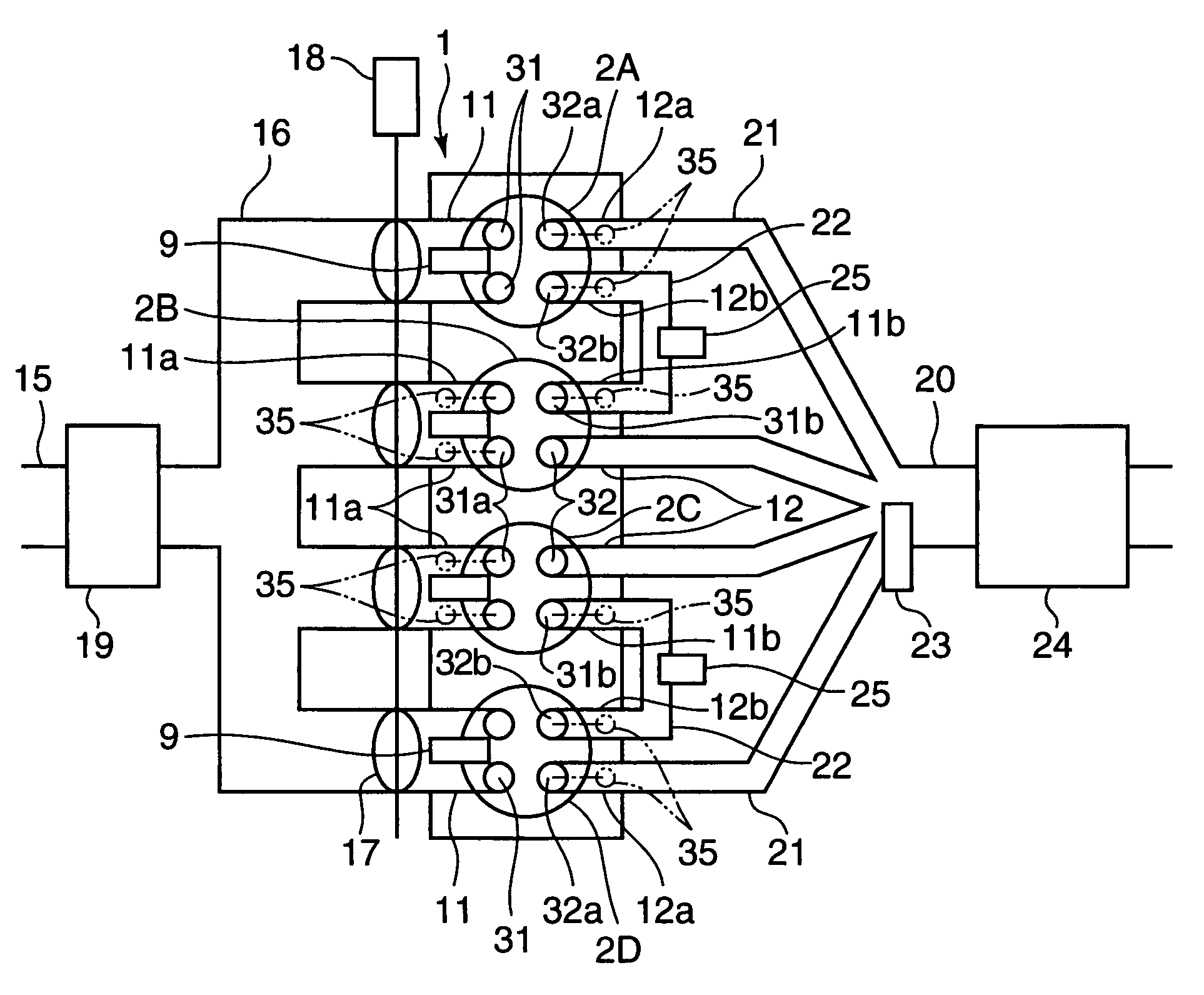
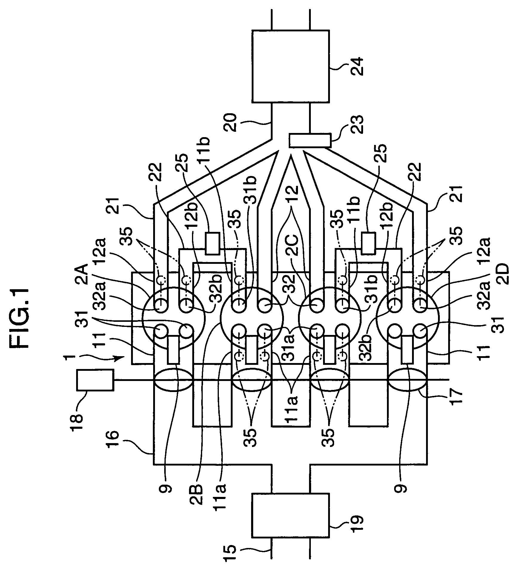
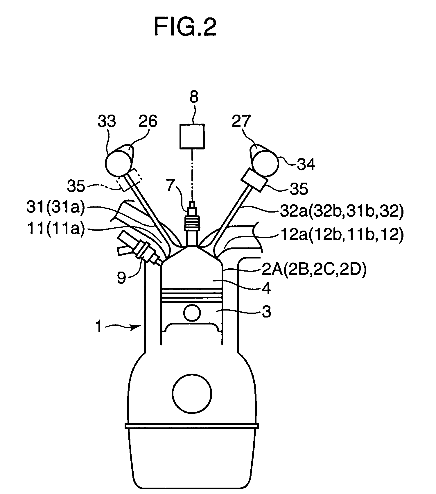
[0029]An embodiment of the present invention will be described below on the basis of the drawings. FIG. 1 shows the schematic constitution of an engine according to an embodiment of the present invention, and FIG. 2 shows in outline the constitution of one cylinder of an engine body 1 and an intake valve, exhaust valve, and the like provided thereon. In these drawings, the engine body 1 comprises a plurality of cylinders, and in the illustrated embodiment comprises four cylinders 2A to 2D. A piston 3 is inserted into each of the cylinders 2A to 2D, and a combustion chamber 4 is formed above the piston 3.

[0030]A spark plug 7 is provided at the apex of the combustion chamber 4 of each cylinder 2A to 2D, and the tip end of the spark plug faces the interior of the combustion chamber 4. An ignition circuit 8 which is capable of controlling the ignition timing through electronic control is connected to the spark plug 7.

[0031]A fuel injector 9 for injecting fuel directly into the combustio...


PUM


Abstract

Burned gas discharged from an exhaust stroke side preceding cylinder of a pair of cylinders having an overlapping exhaust stroke and intake stroke is introduced as is into an intake stroke side following cylinder through an intercylinder gas channel, and only the gas which is discharged from the following cylinder is led into an exhaust passage. Particularly during low loads and idling, combustion is performed in the preceding cylinder at an ultra-lean air-fuel ratio of at least three times the stoichiometric air-fuel ratio, and in the following cylinder, combustion is performed by spark ignition at a substantially stoichiometric air-fuel ratio by feeding fuel to the burned gas introduced from the preceding cylinder. In the following cylinder, combustion is performed through compression ignition in accordance with increases in the load.

Description

BACKGROUND OF THE INVENTION[0001]1. Field of the Invention[0002]The present invention relates to a spark-ignition engine controller, and more particularly to a device for controlling the combustion condition in each cylinder of a multi-cylinder engine in order to improve fuel economy and reduce emissions.[0003]2. Description of the Related Art[0004]Recently, technology has been researched for improving fuel economy in a spark-ignition engine by performing combustion with the air-fuel ratio of the air-fuel mixture in each cylinder set to a lean air-fuel ratio which is larger than the stoichiometric air-fuel ratio. It is also known that by providing a fuel injector for injecting fuel directly into the combustion chamber and performing stratified charge combustion by injecting fuel from the fuel injector in the compression stroke within a low-speed low-load range or the like, ultra lean combustion can be realized (see Japanese Unexamined Patent Application Publication H10-274085, for e...

Claims


Application Information

Patent Timeline
Patent Type & Authority Patents(United States)
IPC IPC(8): F02B11/00F01L1/18F01L1/26F01L13/00F02B1/12F02B15/00F02B17/00F02B23/10F02B47/10F02B75/12F02B75/18F02B75/20F02D13/02F02D13/06F02D21/08F02D41/00F02D41/02F02D41/04F02D41/08F02D41/14F02D41/30F02D41/34F02D43/00F02D45/00F02F1/42F02M25/07F02P5/04F16N3/12
CPCF01L1/267F01L13/0005F01L13/0036F02B17/005F02B47/10F02B75/20F02D13/0203F02D13/06F02D41/0002F02D41/0057F02D41/008F02D41/1475F02D41/3017F02D41/3029F02D41/3035F02F1/4214F02M25/0748F02M25/0752F02P5/045F16N3/12F01L2800/00F01N13/107F02B1/12F02B23/104F02B2075/125F02B2075/1816F02B2275/18F02D41/1454F02D41/1456F02D41/187F02D2041/0017F02M25/0749Y02T10/18Y02T10/123Y02T10/42Y02T10/47F02M26/01F02M26/42F02M26/43Y02T10/12Y02T10/40
Inventor HITOMI, MITSUOSUMIDA, KOUJIHAYASHI, TAKAYOSHI
Owner MAZDA MOTOR CORP
Why Eureka
Try Eureka