Vehicle radiator device

a technology for radiators and vehicles, applied in the direction of machines/engines, lighting and heating apparatus, cycle equipment, etc., can solve the problems of difficult cost reduction and the need for a comparatively large load capacity of elastic supporting means, and achieve the effect of reducing the weight of radiators, reducing the weight of structures, and reducing the load capacity of shrouds

Inactive Publication Date: 2005-12-06
HONDA MOTOR CO LTD
View PDF26 Cites 48 Cited by
  • Summary
  • Abstract
  • Description
  • Claims
  • Application Information

AI Technical Summary

Benefits of technology

[0009]According to this first special feature, the weight of the radiator can be reduced to a large extent because the first and second tanks thereof have been made of light-weight synthetic resin. Also, since the shroud for conducting cooling wind of the radiator has been made of light-weight elastic material, and the radiator has been mounted onto the engine main unit through the shroud, the shroud is capable of performing a vibration isolation function for isolating vibrations from the engine to the radiator in addition to its original function for conducting cooling wind of the radiator. Therefore, there is no need for any vibration isolation means for exclusive use of the radiator, thus making it possible to simplify and reduce the weight of the structure. Moreover, since the radiator is light-weight as described above, the load capacity of the shroud can be reduced, whereby it is possible for the shroud to be thin, further enhancing the vibration isolation function of the structure.
[0010]Also, according to a second special feature of the present invention, the vehicle radiator device is coupled to a vehicle body frame so as to be able to rock in an up-and-down direction through a pivot shaft and is supported through a rear cushion. Since the above-described radiator is coupled to the vehicle body fram...

Problems solved by technology

However, in order to prevent the radiator from being excited by the engine, this conventional radiator must be mounted onto the engine through special elastic supporting m...

Method used


Image

  • Vehicle radiator device
  • Vehicle radiator device
  • Vehicle radiator device

Examples


Embodiment Construction

[0025]Hereinafter, the embodiments of the present invention will be described with reference to one embodiment of the present invention shown in the accompanying drawings.

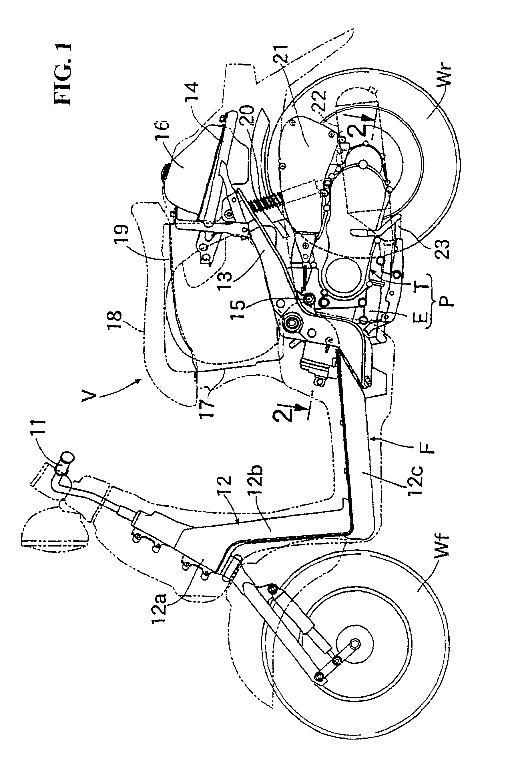
[0026]First, in FIG. 1, a vehicle body frame F of a scooter type motorcycle V having a front wheel Wf to be steered by a steering handlebar 11 and a rear wheel Wr to be driven by a swing type power unit P is divided into three sections: a front frame 12, a center frame 13 and a rear frame 14. Front frame 12 is constituted by a casting of aluminum alloy integrally having a head pipe 12a, a down tube 12b and a step floor 12c. Center frame 13, by which power unit P is supported so as to able to freely rock in an up-and-down direction through a pivot shaft 15, is constituted by a casting of aluminum alloy, and is coupled to the rear end of front frame 12. Rear frame 14 extending upward behind power unit P is constituted by annular pipe material, and a fuel tank 16 is supported by rear frame 14 so as to be surrounded by...


PUM


Abstract

A vehicle radiator device having a radiator with a first tank and a second tank coupled through a heat radiation core. The radiator is mounted onto an engine in a power unit supported by a vehicle body frame. The first and second tanks of the radiator are made of synthetic resin. The radiator is mounted onto the engine through a shroud for conducting cooling wind passing through the radiator. The shroud is made of elastic material for conducting cooling so that vibrations of the engine are absorbed by the elasticity of the shroud, thus preventing vibration of the radiator.

Description

CROSS-REFERENCE TO RELATED APPLICATIONS[0001]The present application claims priority under 35 USC 119 to Japanese Patent Application No. 2000-403153 filed on Dec. 28, 2000 the entire contents thereof is hereby incorporated by reference.BACKGROUND OF THE INVENTION[0002]1. Field of the Invention[0003]The present invention relates to an improvement in a vehicle radiator device having a radiator with a first tank and a second tank coupled through a heat radiation core is mounted onto an engine in a power unit and supported by a vehicle body frame. The first tank communicates to an inlet of a water jacket of the engine, and the second tank communicates to an outlet of the water jacket.[0004]2. Description of Background Art[0005]A vehicle radiator device has been disclosed in, for example, Official Patent Gazette No. 2649179.[0006]This conventional vehicle radiator device is advantageous in simplifying the piping between engine and radiator. However, in order to prevent the radiator from ...

Claims


Application Information

Patent Timeline
IPC IPC(8): B62J99/00F01P3/18F01P5/06F01P11/10F02B61/02F28D1/053
CPCF01P3/18F01P5/06F02B61/02F28D1/05366B62K2202/00F01P2050/16F01P2070/52F28F2255/02Y10S165/905F01P11/10
Inventor OKI, KENJINABEYA, SHINSEKIYA, YOSHIYUKI
Owner HONDA MOTOR CO LTD
Why Eureka
Try Eureka