Ball for ball game and method for manufacturing the same

a ball game and ball technology, applied in the field of ball games, can solve the problems of inability to continuously form sewing lines, the spherical and durability of the reinforcing fabric layer is not achieved, and the sewing work is more difficult and complex, so as to achieve accurate and easy sewn together, the effect of greater bonding strength

Inactive Publication Date: 2005-12-06
MOLTEN CORPORATION +1
View PDF21 Cites 91 Cited by
  • Summary
  • Abstract
  • Description
  • Claims
  • Application Information

AI Technical Summary

Benefits of technology

[0006]The present invention is directed to a ball including a bladder, a fabric layer around the bladder, and an outer skin layer made of a plurality of panels, wherein the fabric layer is formed of fabric pieces whose marginal edges are superimposed, and sewn together. With the above mentioned arrangement, the fabric pieces are sewn together such that the edges of the fabric pieces are superimposed and the tensile strength of the fabric pieces are constantly maintained by a sewing machine. Furthermore, there is no need to turn the two fabric pieces inside out once they have been sewn together. Therefore, sewing work using the sewing machine might not become difficult even if the number of the fabric piece is increased.
[0010]According to one embodiment of the invention, the positioning of the joined portion in the fabric layer corresponds, or substantially corresponds with the positioning of the joined portion of the panels in the outer skin layer. With the above arrangement, the joined portion of the panels in the outer skin layer is positioned on the seaming line of the two fabric pieces having a greater bonding strength due to the overlapping edge portions of the fabric pieces. Therefore, an aperture cannot appear between any one of the panels and the other one of the panels adjacent thereto, and a close contact between the two adjacent panels can be maintained.
[0011]According to one embodiment of the invention, the shape of the pieces in the fabric layer is the same or substantially the same as the shape of a single panel of the outer skin layer, or of two panels of the outer skin layer. With the above arrangement, the joined portion of the pieces in the outer skin layer is positioned on the seaming line of the two fabric pieces having a greater bonding strength due to the overlapping edge portions of the fabric pieces. Therefore, an aperture cannot appear between any one of the panels and the other one of the panels adjacent thereto, and a close contact between the two adjacent panels can be maintained.
[0013]According to one embodiment of the invention, the fabric layer includes a first fabric piece arranged in such a manner that the warp or the weft line is formed along one of three reference circles and a second fabric piece arranged in the center of a triangular region formed by the three reference circles. With the above arrangement, tensile strength of the warp or the weft line is evenly applied to the spherical surface, and serves as a force for maintaining a spherical shape. The pressure applied to the fabric layer from the bladder or the impact load applied from the outside is evenly dispersed across the fabric layer, and the sphericity is maintained even if the pressure is iteratively applied to the fabric layer for a long interval. The second fabric piece is positioned in the center of the triangular region formed by the reference circles, and surrounded by the first fabric piece to be sewn together. The pressure applied to the second fabric piece is dispersed to the first fabric piece. A fabric layer covering the whole surface of the bladder is formed from first and second fabric pieces.
[0014]According to one embodiment of the invention, the fabric layer is made by first attaching the fabric pieces by bonding to form a temporary attachment, and then sewing them together. With the arrangement, the edge portions of the fabric pieces are superimposed, and two adjacent fabric pieces are accurately aligned by temporary attachment, so as to enable the fabric pieces to be sewn together with even tensile strength by a sewing machine. The sewing work using a sewing machine cannot become troublesome even if the number of the fabric pieces sewn together is increased.
[0015]According to one embodiment of the invention, the fabric pieces are sewn together along a guiding line for sewing formed on the fabric pieces by printing. With the above arrangement, the fabric pieces are sewn along the guiding line by the worker, so that the fabric pieces can be accurately and easily sewn together.

Problems solved by technology

However, with this method there is the possibility that the sewing line is not constantly formed.
For this reason, the more the sewing work advances, the more difficult and complex the sewing work becomes.
Due to the difficult sewing work, the resulting reinforcing fabric layer does not have the desired properties of sphericity and durability.
Further, hand sewing is very laborious and trouble some, and it takes much time for hand sewing.

Method used


Image

  • Ball for ball game and method for manufacturing the same
  • Ball for ball game and method for manufacturing the same
  • Ball for ball game and method for manufacturing the same

Examples


embodiment 1

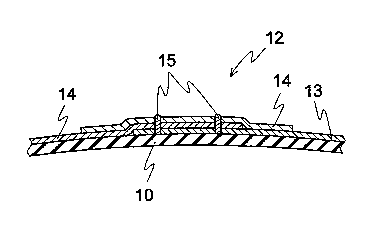
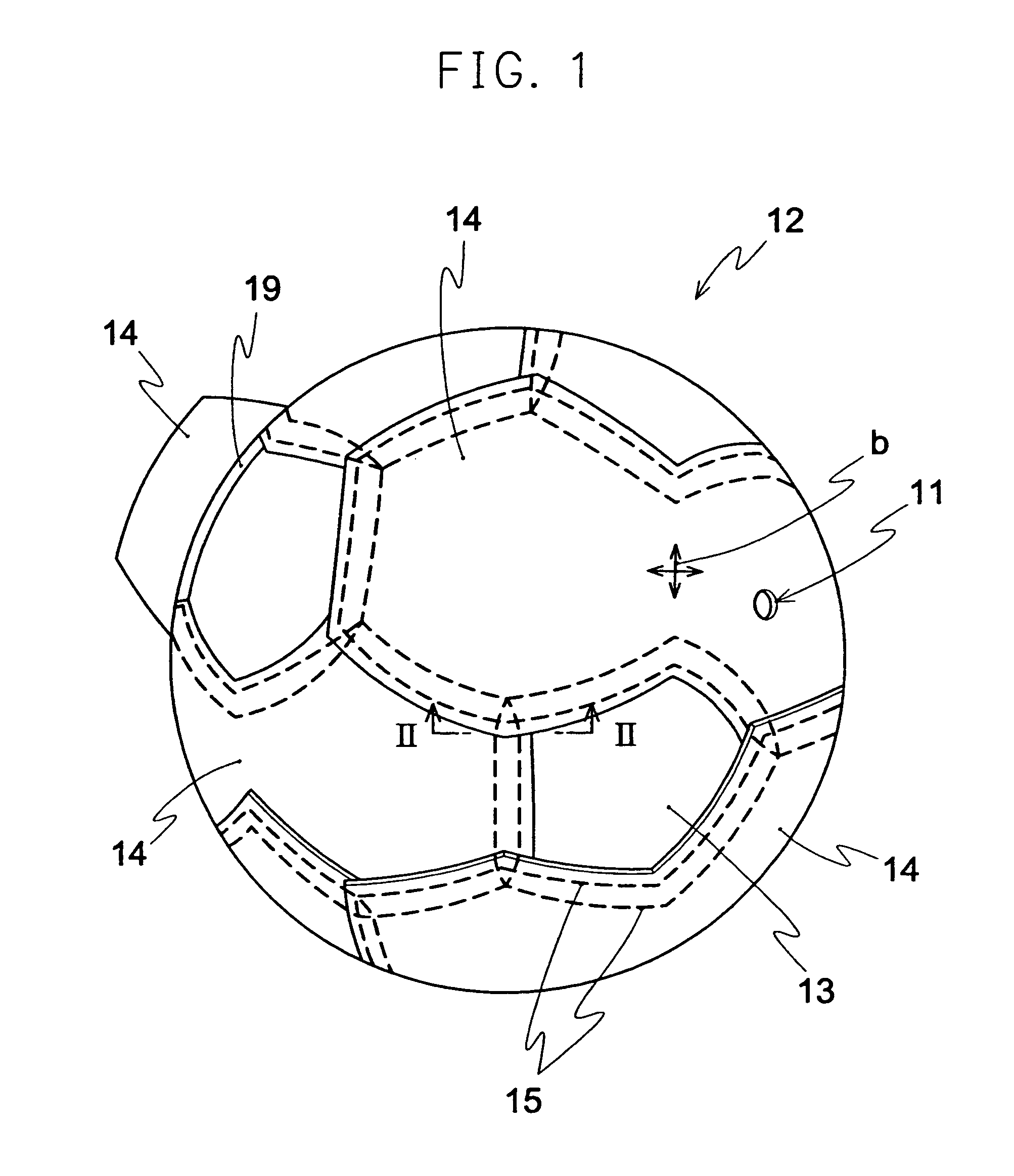
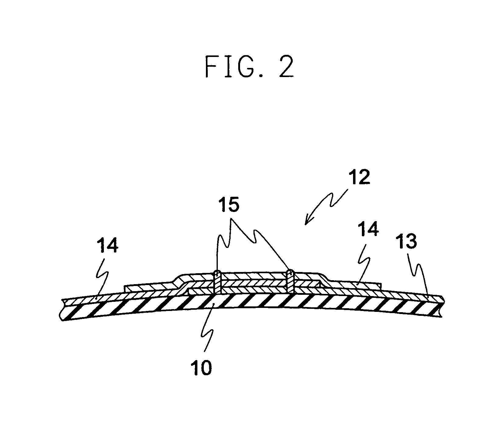
[0035]Hereinafter, EMBODIMENT 1 of the present invention, that is an application of the present invention to a soccer ball will be described with reference to the drawings. Referring to FIGS. 1 through 3, a member indicated by numeral 10 is a bladder having a spherical hollow body, made of a non-air-permeable elastic material such as butyl rubber. The bladder contains compressed air. A member indicated by numeral 11 is a valve hole. Inside this valve hole 11, a valve (not illustrated) is provided, and the compressed air is injected into the bladder 10 via the valve 11 to an inner air pressure of about 1.0 kg / cm2.

[0036]A member indicated by numeral 12 is a woven fabric layer (hereinafter referred to as “fabric layer”) formed to cover a surface of the bladder 10, made of a plurality of fabric pieces (hereinafter referred to as “fabric pieces”) formed into a sphere, serving as a reinforcing layer. The fabric pieces include twelve pentagonal pieces of first fabric pieces 13, and ten hex...

embodiment 2

[0046]EMBODIMENT 2 of the present invention will be explained as mentioned hereinafter. As shown in FIGS. 9 and 10, the fabric layer is deformed in such a manner that spherical shape is formed by sewing ten pieces of a first fabric piece 30 together with twelve pieces of a second fabric piece 31, the second fabric pieces having a pentagonal shape. The first fabric piece 30 is composed of two triangles, one side of one of the two triangles is partially contacted with one side of the other one of the two triangles. In the example shown in FIGS. 9 and 10, length of each side of the triangle can be twice as long as that of the pentagon. Please note that the proportion of the length of each side of the triangle to that of the pentagon can be arbitrarily changed. Numeral 11 shows a valve hole formed in the center of one of the two triangles of the first fabric piece 30.

[0047]Each of the first and the second fabric pieces 30, 31 is laminated in such a manner that two sheets of woven fabric...

embodiment 3

[0049]EMBODIMENT 3 of the present invention will be explained hereinafter. In FIGS. 12 and 13, a fabric layer 12 is composed of twelve pieces of a first fabric piece 35 and eight pieces of a right hexagonal second fabric piece 36. The first fabric piece 35 has a shape corresponding to a right pentagon connected to a right hexagon. In the FIG. 12, the hexagonal parts and the pentagonal parts which correspond to semi-32hedral body are shown by dotted line d. The area lying outside the dotted line d is superimposed with adjacent fabric piece, and sewn together. The first fabric pieces 35 are arranged along three reference circles C, in such a manner that center line P and one of the warp or the weft line b of the first fabric piece are aligned with the reference circle C to cover substantially a quarter of a circle. The first fabric piece 35 has a shape which is symmetrical with the center line P. The seaming line positioned on one of the reference circles C (being the seam of two adjo...


PUM


Abstract

To provide a ball for ball game and a method for manufacturing the ball having superior sphericity, an ability to retain its original shape, durability, and soft feel. The fabric layer (12) is formed by sewing with a sewing machine for instance pentagonal first fabric pieces (13) together with composite shaped second fabric pieces (14) in which two hexagons are connected with each other, so that a spherical shape is formed. The marginal edge of the first and second fabric pieces are superimposed in the spherical surface direction, so that corner portions thereof are temporarily attached. Temporary attachment is achieved by inserting the needle into the needle through hole formed in the corner of the first and second fabric pieces, and welding by means of ultra sonic wave, such that the first and second fabric pieces (13, 14) are accurately aligned. The temporarily attached fabric pieces sewn together using a sewing machine along the guiding line (17) for sewing printed beforehand on the surface of the fabric pieces (13, 14).

Description

TECHNICAL FIELD[0001]The present invention relates to a ball for ball game and method for manufacturing the ball for ball game particularly for such games as soccer, handball and volleyball.BACKGROUND ART[0002]Conventionally, an air-inflated ball manufactured for the ball sports comprises a rubber bladder for containment of air, a reinforcing layer formed around the bladder for rendering the ball spherical and durable, and a skin layer made of a plurality of leather panels bonded to the reinforcing layer. The reinforcing layer is typically made of twelve generally trapezoidal pieces of fabric each having outer edges sewn with another to form a generally spherical shape (Japanese Unexamined Patent Publication No. 236568 / 1987).[0003]FIGS. 14 and 15 show the structure disclosed in the Gazette mentioned above. Specifically, a generally trapezoidal piece of fabric 1 is paired with another and sewn to each other in mirror symmetry to form an equilateral quadrilateral 2. A total of six equ...

Claims


Application Information

Patent Timeline
Patent Type & Authority Patents(United States)
IPC IPC(8): A63B41/08A63B45/00
CPCA63B41/08A63B45/00
Inventor SHISHIDO, HIDEOMI
Owner MOLTEN CORPORATION
Why Eureka
Try Eureka