Method of making a cutting instrument having integrated sensors

a technology of cutting instruments and sensors, applied in the field of cutting instruments, can solve the problems of severe adverse effects, complex task, and failure to properly classify tissue before making incisions, and achieve the effects of improving the safety and safety of surgical procedures, reducing the risk of surgical complications, and improving the safety of surgical procedures

Inactive Publication Date: 2005-12-06
VERIMETRA
View PDF45 Cites 1252 Cited by
  • Summary
  • Abstract
  • Description
  • Claims
  • Application Information

AI Technical Summary

Benefits of technology

[0013]Described is a cutting instrument including a rigid blade having a recess formed therein and a semiconductor substrate affixed to the blade in the recess. The blade is preferably constructed of metal. The semiconductor substrate includes at least one sensor formed thereon. The sensor form

Problems solved by technology

Surgery continues to be one of the most delicate and risky medical procedures.
This task is greatly complicated by the fact that human anatomy differs slightly from person to person.
The failure to properly classify tissue before making an incision can have severe adverse consequences.
For example, if a surgeon fails to properly clas

Method used


Image

  • Method of making a cutting instrument having integrated sensors
  • Method of making a cutting instrument having integrated sensors
  • Method of making a cutting instrument having integrated sensors

Examples


Embodiment Construction

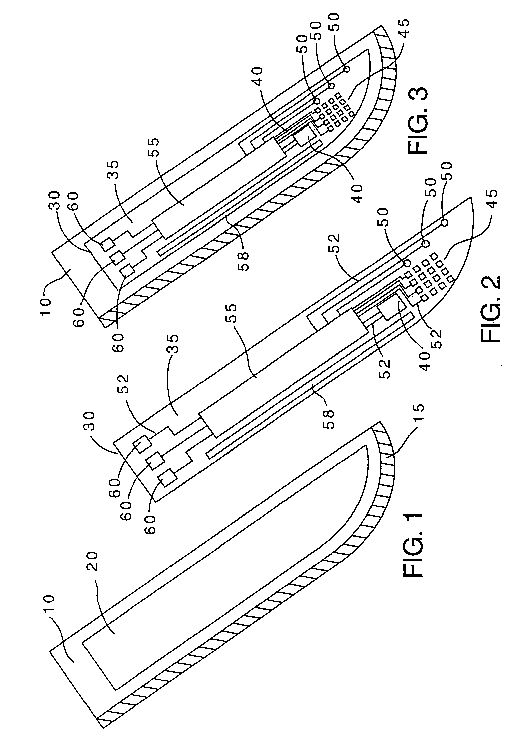
[0035]Referring to FIG. 1, blade 10, preferably made of a metal such as stainless steel, includes sharp edge 15 and recess 20 formed therein. As shown in FIG. 1, the shape of recess 20 preferably follows the shape of edge 15 of blade 10 so as to maximize the ability to increase the density of the sensors located at or near edge 15. Recess 20 can be formed in blade 10 by one of several well known methods including grinding, milling, chemical etching, water-jet machining, stamping, or electron discharge machining. Although only a single recess 20 is shown on a single side of blade 10 in FIG. 1, it should be understood that recess 20 may be formed on either one of the sides of blade 10, or both sides of blade 10. Additionally, multiple recesses of the same or different size and / or arrangement may be formed on one or both sides of blade 10.

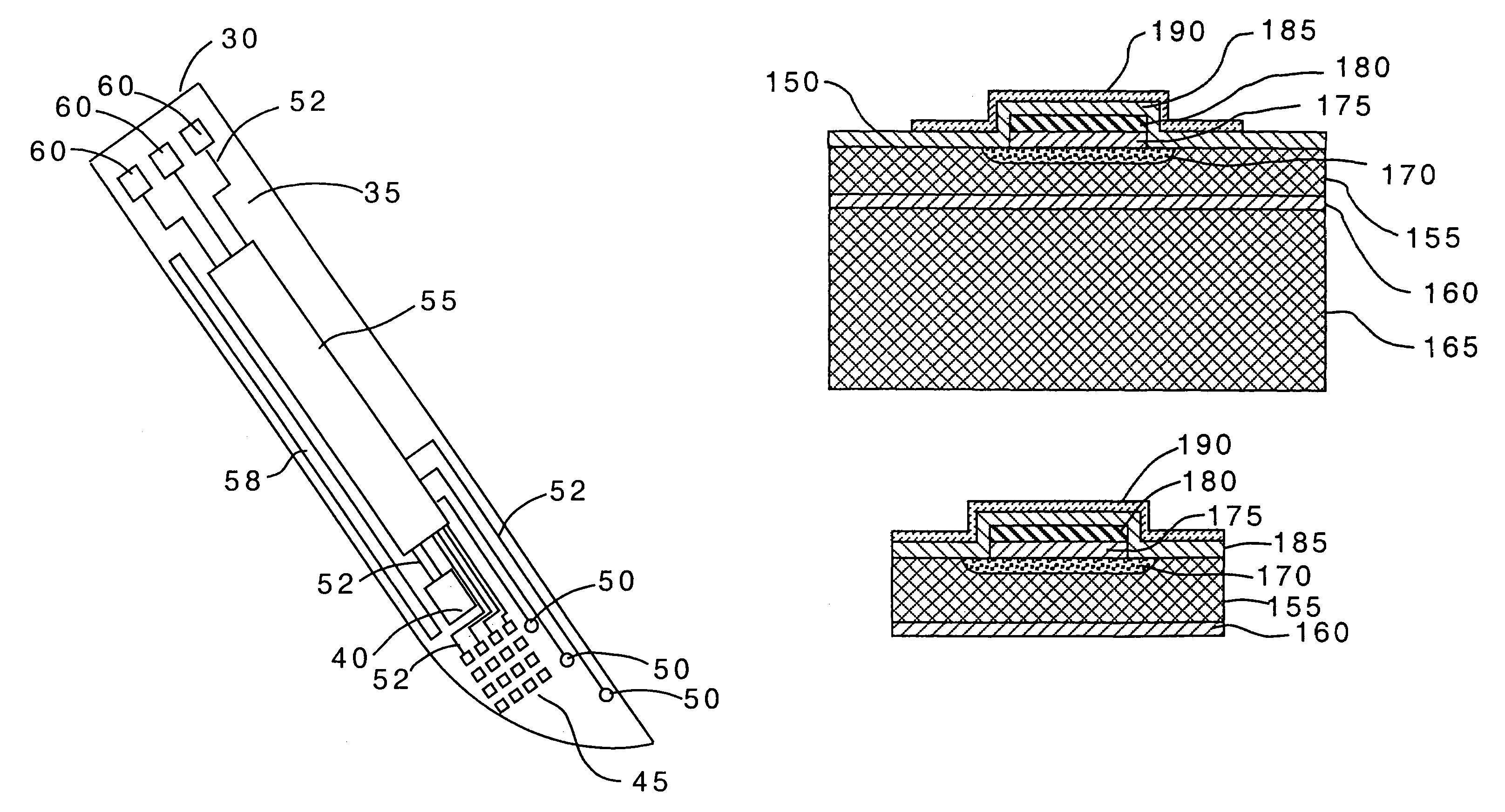
[0036]Referring to FIG. 2, a sensor element 30 is shown. Sensor element 30 includes semiconductor substrate 35, preferably made of silicon. Formed on...


PUM


Abstract

A cutting instrument including a metal blade has a recess formed therein and a semiconductor substrate affixed to the blade in the recess. The semiconductor substrate includes at least one sensor formed thereon. The sensor formed on the semiconductor substrate may comprise at least one or an array of a strain sensors, pressure sensors, nerve sensors, temperature sensors, density sensors, accelerometers, and gyroscopes. The cutting instrument may also further include a handle wherein the blade is affixed to the handle and the semiconductor substrate is electrically coupled to the handle. The handle may then be coupled, either physically or by wireless transmission, to a computer that is adapted to display information to a person using the cutting instrument based on signals generated by one or more of the sensors formed on the semiconductor substrate. The computer or handle may also be adapted to store data based on the signals generated by one or more of the sensors. A method of making said cutting instrument includes the steps of at least one sensor being formed on a semiconductor wafer and a layer of photoresist being applied on a top side of the semiconductor wafer according to a pattern that matches the defined shape of the semiconductor substrate. The portion of the semiconductor wafer not covered by the photoresist is removed and thereafter the photoresist is removed from the semiconductor wafer, thereby leaving the semiconductor substrate having a defined shape and at least one sensor formed thereon. The semiconductor substrate having a defined shape and at least one sensor formed thereon is then affixed to a metal blade in a recess formed in said blade.

Description

[0001]This application is a divisional of Ser. No. 09 / 626,273, filed Jul. 25, 2000, now U.S. Pat. No. 6,494,882.FIELD OF THE INVENTION[0002]The present invention relates to a cutting instrument having a variety of sensors integrated therein. More particularly, the invention relates to a blade having a sensor or sensors formed thereon, wherein the sensors are mounted adjacent the cutting surface to allow measurement of the physical characteristics of the blade and a workpiece or tissue.BACKGROUND OF THE INVENTION[0003]Cutting instruments exist for a myriad of applications, ranging from very specialized applications such as surgical scalpels, to industrial applications and common consumer applications.[0004]Surgery continues to be one of the most delicate and risky medical procedures. Before making an incision into tissue, surgeons are required to identify what type of tissue is being incised, such as fatty, muscular, vascular or nerve. This task is greatly complicated by the fact tha...

Claims


Application Information

Patent Timeline
IPC IPC(8): B26B11/00A61B17/00A61B17/04A61B17/32A61B17/34A61B18/14A61B19/00
CPCA61B17/32A61B17/3211A61B18/1402A61B2017/00022A61B2017/00084A61B2017/00128A61B2019/464A61B2019/4873A61B2090/064A61B2090/0814
Inventor LEBOUITZ, KYLE S.MIGLIUOLO, MICHELE
Owner VERIMETRA
Why Eureka
Try Eureka