
Method and apparatus for provisioning and monitoring internet protocol quality of service

a technology of internet protocol and quality monitoring, applied in the field of method and apparatus for provisioning and monitoring internet protocol quality of service, to achieve the effect of minimal utilization of links

Inactive Publication Date: 2005-12-06
AMERICAN TELEPHONE & TELEGRAPH CO
View PDF13 Cites 82 Cited by
  • Summary
  • Abstract
  • Description
  • Claims
  • Application Information

AI Technical Summary

Benefits of technology

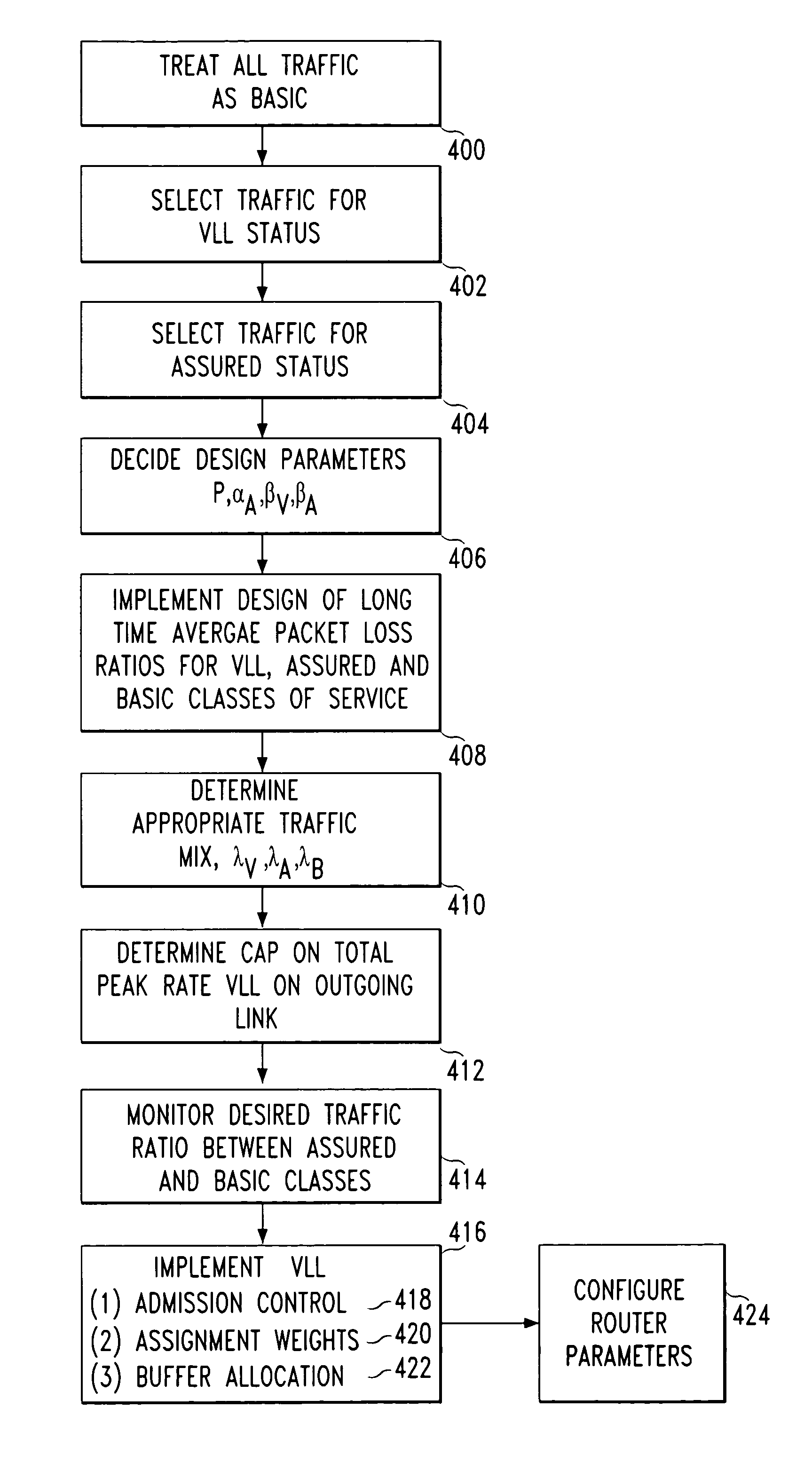
[0011]For a three-service class QoS scheme comprising a Virtual Leased Line, Assured and Basic service classes, the resource management system optimizes packet traffic flow from (1) the values for the maximum QoS deterioration levels of the traffic caused by individual reservations for Virtual Leased Line traffic, (2) the maximum QoS deterioration levels of the Basic service caused by the Assured service, and (3) the packet loss ratios of the Assured versus the Basic services. These values provide information necessary for determining capacity planning and provide the minimum utilization of a link to be considered when congestion occurs. Average utilization of Virtual Leased Line traffic with respect to the peak rate subscribed along each link is computed versus the maximum percentage of the total Virtual Leased Line subscription with respect to the link capacity. Preconfiguration of all the routers with parameter settings for Weighted Fair Queuing (WFQ), buffer allocations, and Weighted Random Early Discard (WRED) further allows the resource reservation system to maintain the desired QoS in the network.

Problems solved by technology

However, this optimization should not erode the lowest levels of service such that packet delivery delays for lower classes of services are so long that the lower classes of services cease to deliver the level of subscribed service.

Method used


Image

  • Method and apparatus for provisioning and monitoring internet protocol quality of service
  • Method and apparatus for provisioning and monitoring internet protocol quality of service
  • Method and apparatus for provisioning and monitoring internet protocol quality of service

Examples


Embodiment Construction

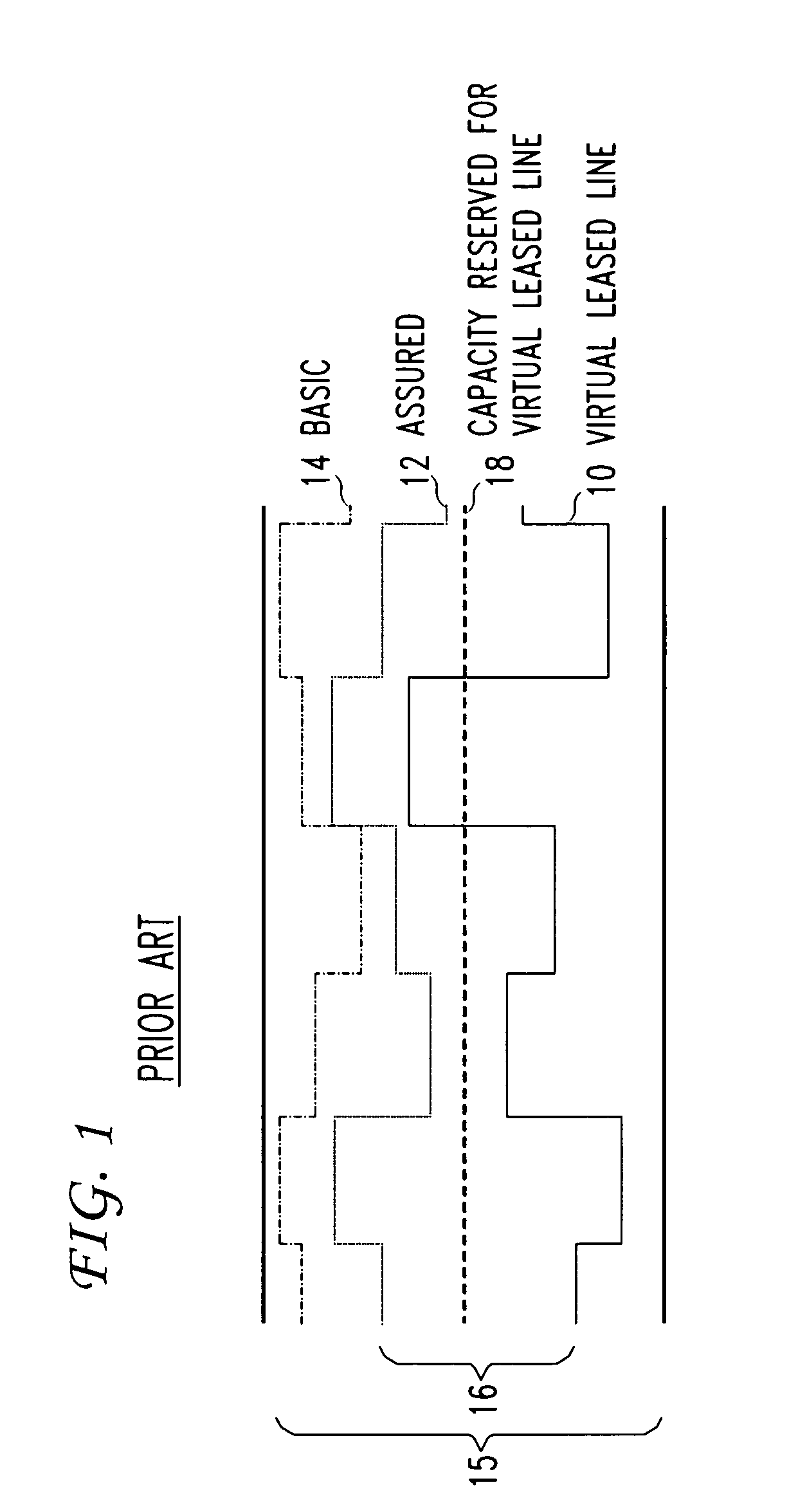
[0023]FIG. 1 illustrates the three classes of services: Virtual Leased Line (10), Assured (12) and Basic (14) services supported across a data line of fixed bandwidth (15) for Quality of Service (QoS) functionality. These three classes of services have different characteristics in order to satisfy the service demands of a user. At the highest level in the QoS hierarchy, Virtual Leased Line service (10) is designed for applications and customers that require predictable point-to-point performance. A Virtual Leased Line (10) is a point-to-point data line with a guaranteed peak transmission rate. Implementing performance restrictions and setting criteria on the line, packet loss due to network congestion, delay, and delay-jitter is minimized. Examples of applications employing Virtual Leased Line level of service (10) include Voice over Internet Protocol (VoIP), transaction processing, and multimedia applications that require low delay and jitter.

[0024]The second class of service in th...


PUM


Abstract

An architecture, design, and realization for providing Quality of Service (QoS) to Internet Protocol (IP) networks based on a three-class differentiated service scheme where the service provider uses a resource management system and a schedule optimizer to enable the optimal use of bandwidth and buffer resources at each node or router along the various links between the ingress and egress points in a network. The resource reservation system checks to determine if sufficient bandwidth resources are available along the path requested by the customer for a particular class. The schedule optimizer ensures that sufficient buffer resource allocations and parameter settings are made to optimally reach the predetermined QoS criteria for each of the three classes. The system also contains a mechanism supporting resource reservations providing additional resources along alternative paths if the selected path links fail in the network.

Description

CROSS-REFERENCE TO RELATED APPLICATIONS[0001]This is a continuation of U.S. patent application Ser. No. 09 / 475,512 filed Dec. 30, 1999, now U.S. Pat. No. 6,744,767.FIELD OF THE INVENTION[0002]This invention relates to a method and apparatus for allocating bandwidth during implementation of Quality of Service (QoS) using Internet Protocol (IP) provisioning. Specifically, the invention allocates bandwidth resources between service classes and during network congestion either buffers or randomly drops packets of lower quality of services to ensure delivery with minimized packet loss for higher quality of services.BACKGROUND[0003]Quality of Service (QoS) mechanisms for packet transmission typically utilize data path mechanisms (packet classification, policing, shaping, buffering, and scheduling) and control path mechanisms (signaling, resource reservation, routing) for ensuring packet delivery during periods of network congestion. Currently within the networking community there exist tw...

Claims


Application Information

Patent Timeline
IPC IPC(8): H04L12/56
CPCH04L12/5693H04L12/5695H04L45/123H04L45/22H04L45/30H04L47/10H04L47/20H04L47/2408H04L47/29H04L47/30H04L47/326H04L47/521H04L47/6225H04L47/6265H04L47/724H04L47/728H04L47/765H04L47/801H04L47/805H04L47/808H04L47/822H04L47/825H04L47/50H04L47/70H04L45/247
Inventor CHIU, ANGELA L.CIVANLAR, SEYHANGREENBERG, ALBERT GORDONTANG, ZHUANGBO
Owner AMERICAN TELEPHONE & TELEGRAPH CO
Learn More