Bright pointer for instrument cluster

a bright pointer and instrument cluster technology, applied in instruments, machines/engines, transportation and packaging, etc., can solve the problems of small portion of light flux reaching the pointer, difficulty in achieving even luminance along the length of the pointer for this light source configuration, and insufficient light intensity for special instrument panel applications. achieve the effect of increasing brightness

Inactive Publication Date: 2005-12-13
SIEMENS VDO AUTOMOTIVE CORP
View PDF18 Cites 11 Cited by
  • Summary
  • Abstract
  • Description
  • Claims
  • Application Information

AI Technical Summary

Benefits of technology

[0008]A display cluster for a vehicle instrument panel includes a light guide and a light source that is directly incorporated into the light guide. The light guide moves relative to a graphical image supported by a display surface. The light source illuminates at least a portion of the light guide to indicate a vehicle operating condition displayed by the graphical image. A non-contact coupling transfers power from a circuit board to the light source. This combination provides increased brightness for the light guide while eliminating the need for mechanical connections between a moving light source and the stationary circuit board.

Problems solved by technology

One disadvantage with this configuration is that only a very small portion of the light flux reaches the pointer.
Further, the light intensity is not high enough for special instrument panel applications, such as a black panel cluster, for example.
It is also difficult to achieve even luminance along the length of the pointer for this light source configuration.
One disadvantage with this configuration is that the mechanical connections are expensive.
Further, this configuration requires an intensive manufacturing process, and assembly is difficult.
Also, due to the movement of the mechanical connections in response to movement of the pointer, the active pointer system is not always reliable.
This painting process increases cost and results in additional operational steps that must be performed during production.

Method used


Image

  • Bright pointer for instrument cluster
  • Bright pointer for instrument cluster
  • Bright pointer for instrument cluster

Examples


Embodiment Construction

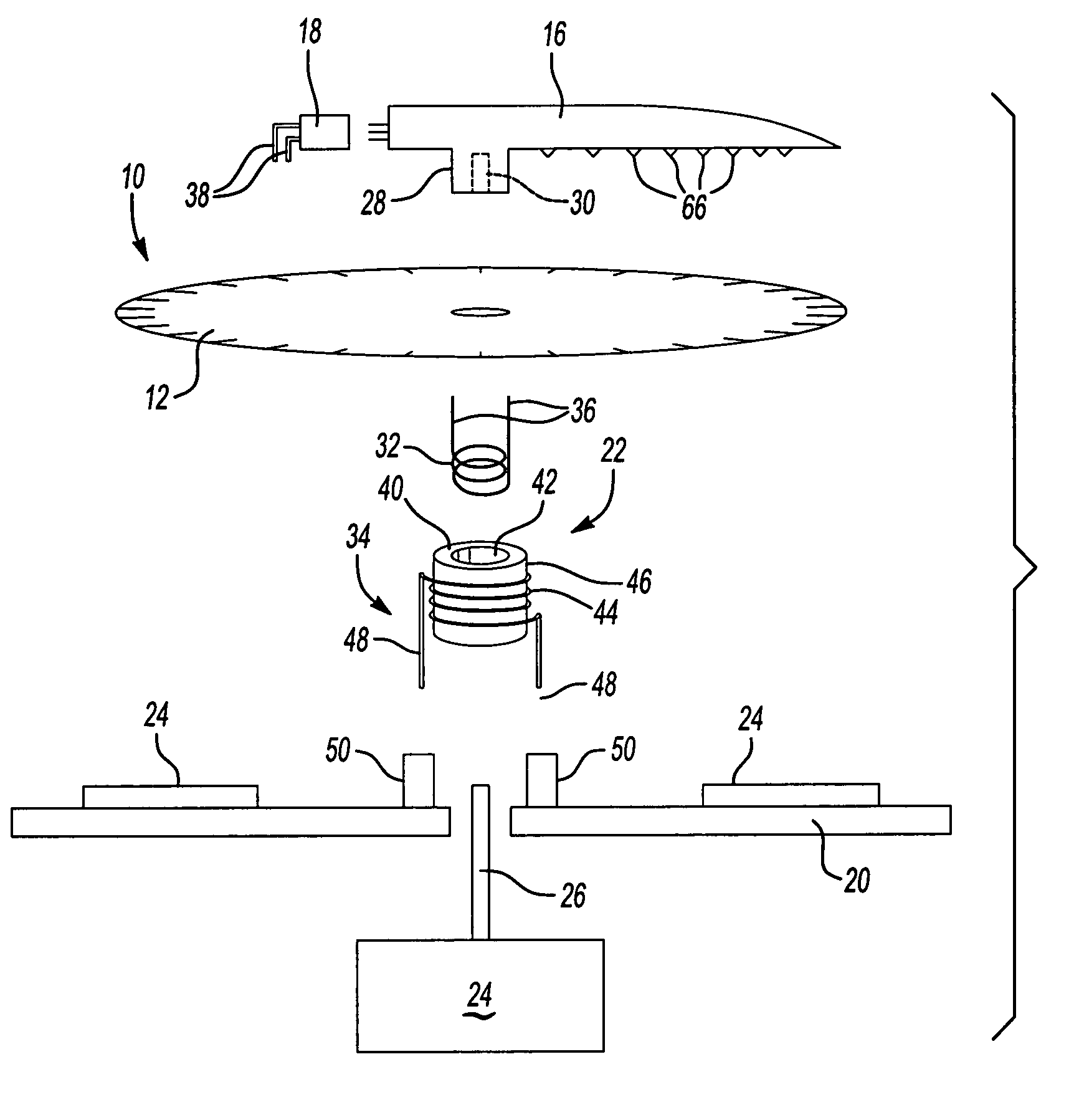
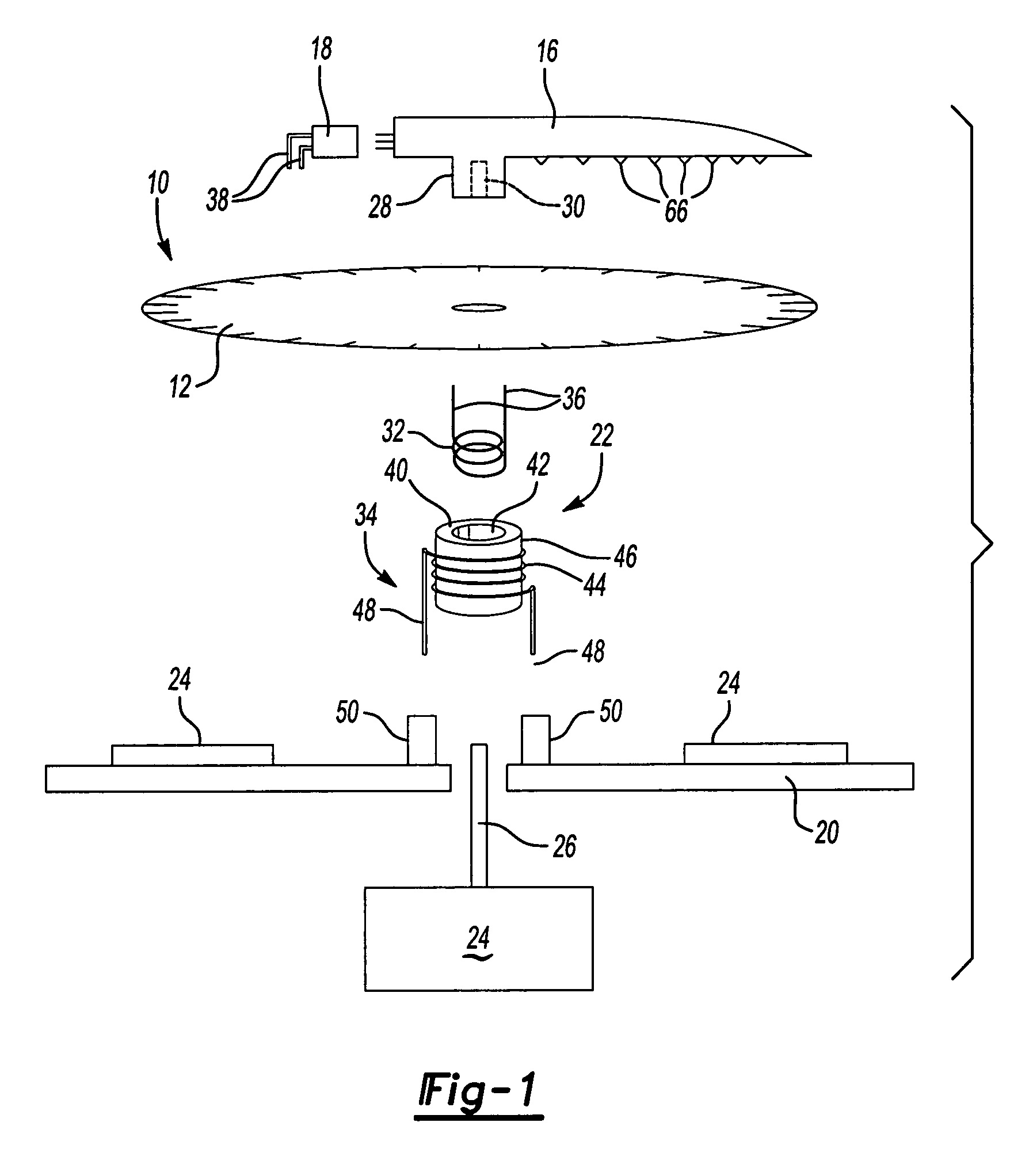
[0016]An instrument cluster including at least one gauge assembly is shown generally at 10 in FIG. 1. The assembly 10 includes a dial 12 that includes a graphical image, such as a scale, for example, which is used to indicate a vehicle operating condition. The dial 12 is mounted to a dash panel or other similar fixed vehicle structure 14 (see FIG. 2). A light guide or pointer 16 is mounted for selective movement relative to the dial 12 and is used to indicate the current status of the vehicle operating condition. A light source 18 is used to illuminate at least a portion of the light guide 16 so that a vehicle operator can clearly see the vehicle operating condition. The light source 18 can illuminate the length of the light guide 16, can illuminate only the tip of the light guide 16, or any other portion thereof. The light source 18 could be an LED or any other light source known in the art.

[0017]The light source 18 is mounted directly to the moving light guide 16. This increases t...


PUM


Abstract

An instrument display for a vehicle dash includes a unique light source and light guide assembly. The light source is incorporated directly into the light guide. A non-contact magnetic coupling transfers power from a circuit board to the light source. A textured surface is formed on one portion of the external surface of the light guide to evenly illuminate the light guide. Also, surface roughness on an opposing external surface portion of the light guide is varied depending on the length of the light guide to provide similar luminance for light guides having different lengths.

Description

CROSS-REFERENCE TO RELATED APPLICATIONS[0001]The application claims priority to U.S. Provisional Application No. 60 / 433,201, which was filed on Dec. 12, 2002.BACKGROUND OF THE INVENTION[0002]This invention relates to a method and apparatus that illuminates a light guide with a light source mounted to the light guide where the light source is powered through a non-contact coupling that electrically connects the light source to a circuit board.[0003]Instrument clusters for a vehicle are traditionally located on a vehicle dashboard and include several gauges that indicate various vehicle operating conditions. For example, an instrument cluster may include a speedometer, a tachometer, an engine condition indicator, and other known types of gauges. A panel is mounted to a vehicle structure and typically supports graphical images for the gauges indicating the various vehicle operating conditions. A pointer is mounted for movement relative to each graphical image. The pointer is operably c...

Claims


Application Information

Patent Timeline
Patent Type & Authority Patents(United States)
IPC IPC(8): G01D11/28G01D13/22G12B11/04
CPCB60K37/02G01D11/28G01D13/22G12B11/04B60K2350/1064B60K2350/203B60K2370/154B60K2370/33B60K2370/698
Inventor BIRMAN, VYACHESLAV B.ECKARDT, WERNERTAO, QIMOELL, MARCUS
Owner SIEMENS VDO AUTOMOTIVE CORP
Why Eureka
Try Eureka