Rotary cutting tool

a cutting tool and rotary cutting technology, applied in the direction of band saws, manufacturing tools, saw chains, etc., can solve the problem of unbalanced cutting force of axial components of cutting tools

Inactive Publication Date: 2005-12-13
ISCAR LTD
View PDF19 Cites 31 Cited by
  • Summary
  • Abstract
  • Description
  • Claims
  • Application Information

AI Technical Summary

Benefits of technology

[0002]It is an object of the present invention to provide a cutting tool of the above general nature that replaces each group of cutting inserts arranged in a staggered formation by a single indexable cutting insert giving rise to a balanced cutting tool with respect to the axial component cutting forces.

Problems solved by technology

Since the cutting inserts are staggered, the cutting tool is unbalanced with respect to the axial component cutting forces.

Method used


Image

  • Rotary cutting tool
  • Rotary cutting tool
  • Rotary cutting tool

Examples


Embodiment Construction

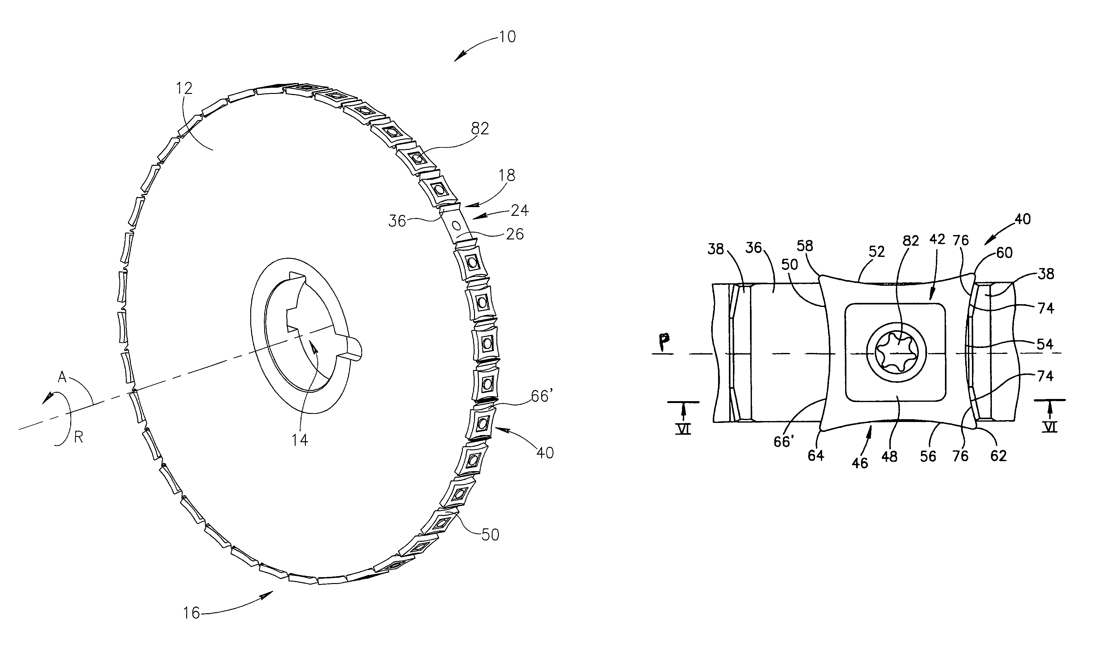
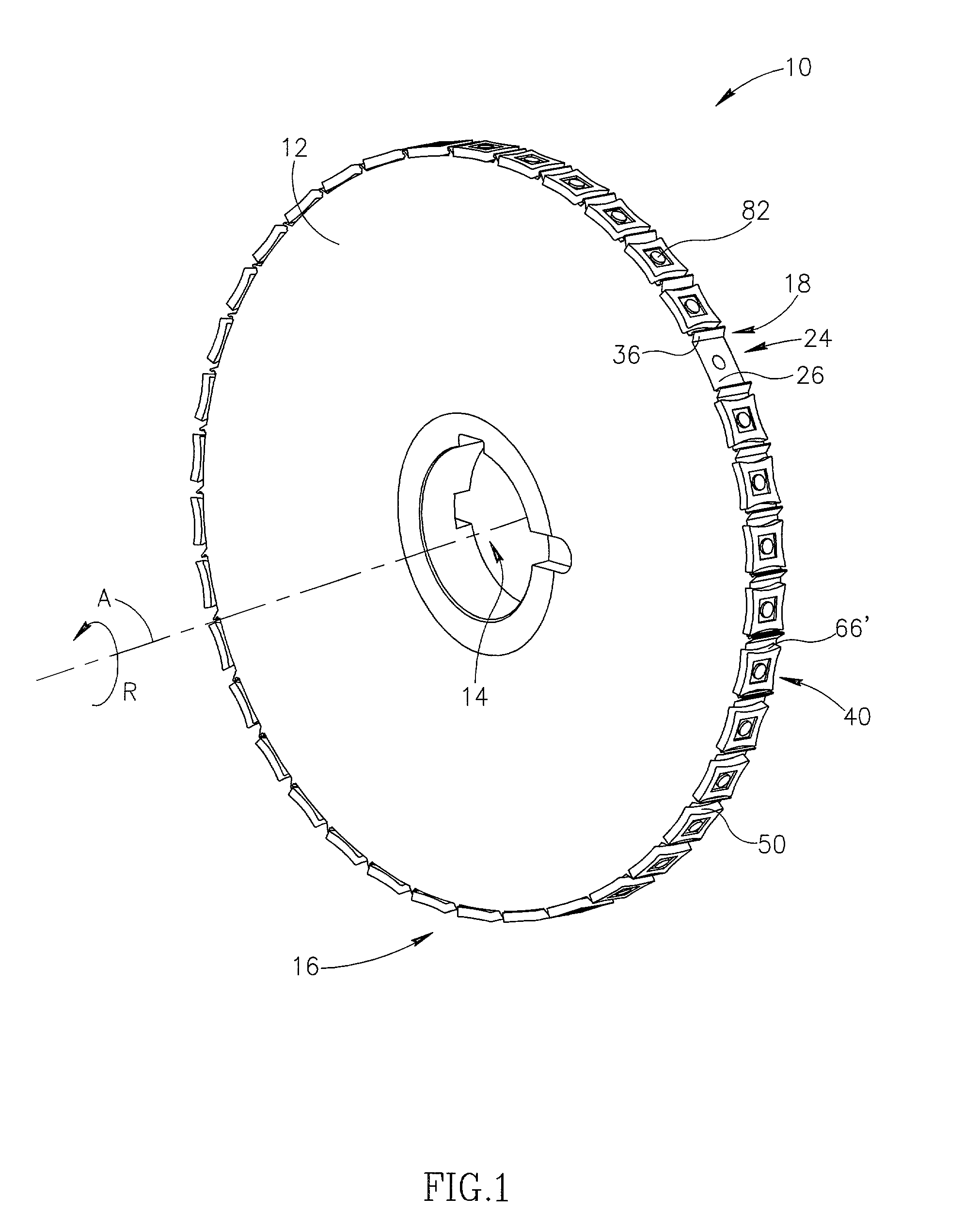
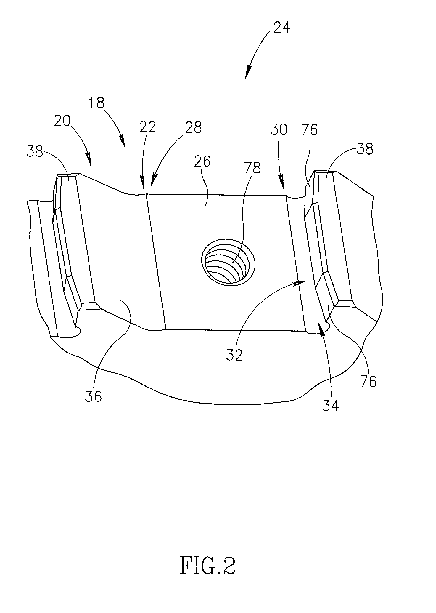
[0020]Attention is drawn to the drawings in general and to FIG. 1 in particular, showing a rotary cutting tool in accordance with the present invention. The rotary cutting tool 10 comprises a tool body 12 in the form of a circular disk having a center 14 and a periphery 16. The rotary cutting tool 10 has an axis of rotation A that passes through the center 14 of the tool body 12, the axis of rotation defining the tool's plane of rotation P. The tool body 12 has a plurality of chip clearance recesses 18 opening outwardly from and spaced angularly around the tool body 12 periphery 16, each chip clearance recess having a leading end 20 and a trailing end 22. It will be appreciated that the leading end 20 precedes the trailing end 22 with respect to the direction of rotation R of the rotary cutting tool 10.

[0021]Associated with each chip clearance recesses 18 is an insert receiving pocket 24. All the insert receiving pockets are at the same radial distance from the center 14 of the tool...


PUM

PropertyMeasurementUnit
thicknessaaaaaaaaaa
diameteraaaaaaaaaa
diameteraaaaaaaaaa

Abstract

A rotary cutting tool having the general form of a circular disk with cutting inserts secured tangentially to the circumference of the tool's body, for metal machining in general and for machining cam lobes. The cutting inserts have concave side surfaces and concave cutting edges.

Description

FIELD AND BACKGROUND OF THE INVENTION[0001]This invention relates to rotary cutting tools having a tool body the general form of a circular disk with cutting inserts secured tangentially to the circumference of the tool body, for metal machining in general and for machining cam lobes of camshafts of internal combustion engines in particular. Such cutting tools normally employ groups of two or more cutting inserts arranged in a circumferentially staggered formation. The individual cutting edges of the cutting inserts in each group are generally oriented at non-zero lead angles. Consequently, each cutting insert has a non-zero axial component cutting force acting on it. Since the cutting inserts are staggered, the cutting tool is unbalanced with respect to the axial component cutting forces.SUMMARY OF THE INVENTION[0002]It is an object of the present invention to provide a cutting tool of the above general nature that replaces each group of cutting inserts arranged in a staggered form...

Claims


Application Information

Patent Timeline
Patent Type & Authority Patents(United States)
IPC IPC(8): B23C5/08B23C5/20B23C5/22B23D61/06
CPCB23C5/08B23C5/202B23D61/06B23C2200/367Y10T407/23B23C2200/0466Y10T407/1924Y10T83/9319Y10T83/9329B23C5/20
Inventor SATRAN, AMIREISEN, YARON
Owner ISCAR LTD
Why Eureka
Try Eureka