Intervertebral implant for transforaminal posterior lumbar interbody fusion procedure

a transforaminal posterior lumbar interbody and interbody technology, applied in the field of intervertebral implants, can solve the problems of easy insertion of implants, limited lateral inserting of implants, severe low back pain, etc., and achieve the effect of facilitating insertion and preventing slippag

Inactive Publication Date: 2005-12-13
DEPUY SYNTHES PROD INC +1
View PDF161 Cites 401 Cited by
  • Summary
  • Abstract
  • Description
  • Claims
  • Application Information

AI Technical Summary

Benefits of technology

[0007]The present invention relates to an intervertebral implant (“T-PLIF implant”) and its use during a transforaminal lumbar interbody fusion procedure. In a preferred embodiment, the T-PLIF implant has an arcuate body with curved, preferably substantially parallel, posterior and anterior faces separated by two narrow implant ends, and superior and inferior faces having textured surfaces for contacting upper and lower vertebral endplates. Preferably, the textured surfaces comprise undulating structures which may include projections, such as teeth, of a saw-tooth or pyramidal configuration, or ridges which preferably penetrate the vertebral endplates and prevent slippage. The narrow implant ends may be rounded or substantially flat. The arcuate implant configuration facilitates insertion of the implant via a transforaminal window. The implant, which may be formed of allogenic bone, metal, or plastic, may also have at least one depression, such as a channel or groove, in the posterior or anterior face for engagement by an insertion tool, such as an implant holder. In a preferred aspect, the superior and inferior faces are convex, and the thickness of the implant tapers with its greatest thickness in the middle region between the narrow ends of the implant, i.e., at a section parallel to a sagittal plane, and decreasing toward each of the narrow ends.
[0009]In another preferred embodiment, the implant is formed of a plurality of interconnecting bodies assembled to form a single unit. In this configuration, the plurality of interconnecting bodies forming the T-PLIF implant may be press-fit together and may include one or more pin(s) or screw(s) extending through an opening in the plurality of bodies to hold the bodies together as a single unit. Adjacent surfaces of the plurality of bodies may also have mating interlocking surfaces that aid in holding the bodies together as a single unit.

Problems solved by technology

A number of medical conditions such as compression of spinal cord nerve roots, degenerative disc disease, herniated nucleus pulposus, spinal stenosis and spondylolisthesis can cause severe low back pain.
The T-PLIF approach avoids damage to nerve structures such as the dura, cauda equina and the nerve root, but the resulting transforaminal window available to remove the affected disc, prepare the vertebral endplates, and insert the implant is limited laterally by soft tissue and medially by the cauda equina.
However, as these devices were not designed specifically for the T-PLIF procedure, they are not shaped to be easily insertable into the affected disc space through the narrow transforaminal window, and may require additional retraction of the cauda equina and nerve roots.
Such retraction can cause temporary or permanent nerve damage.
In addition, some of these implants, such as the threaded titanium or polymer cage, suffer from the disadvantage of requiring drilling and tapping of the vertebral endplates for insertion.
Further, the incidence of subsidence in long term use is not known for such cages.
Finally, restoration of lordosis, i.e., the natural curvature of the lumbar spine is very difficult when a cylindrical or square titanium or polymer cage is used.

Method used


Image

  • Intervertebral implant for transforaminal posterior lumbar interbody fusion procedure
  • Intervertebral implant for transforaminal posterior lumbar interbody fusion procedure
  • Intervertebral implant for transforaminal posterior lumbar interbody fusion procedure

Examples


Embodiment Construction

[0052]While various descriptions of the present invention are provided below, it should be understood that these descriptions are intended to illustrate the principals of the present invention and its various features, which can be used singly or in any combination thereof. Therefore, this invention is not to be limited to only the specifically preferred embodiments described and depicted herein.

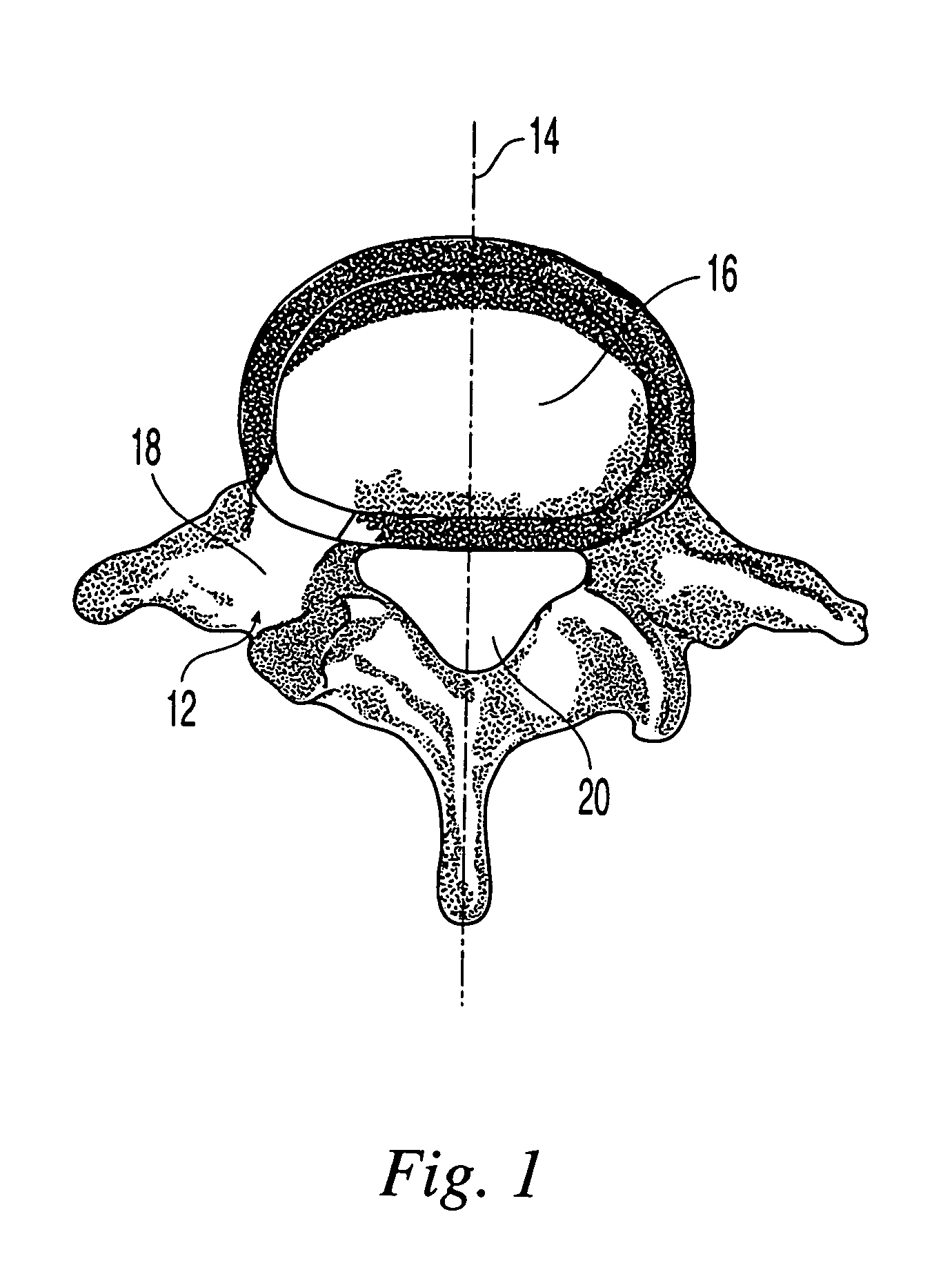
[0053]The transforaminal posterior lumbar interbody fusion implant (“T-PLIF implant”) is designed for use as an intervertebral spacer in spinal fusion surgery where an affected disk is removed from between two adjacent vertebrae and replaced with an implant that provides segmental stability and allows for bone to grow between the two vertebrae to bridge the gap created by disk removal. Specifically, the T-PLIF implant is designed for the transforaminal lumbar interbody fusion (T-PLIF) technique, which, as shown in FIG. 1, involves a posterior approach 12, offset from the midline 14 of the sp...


PUM


Abstract

An intervertebral implant for fusing vertebrae is disclosed. The implant has a body with curved, substantially parallel posterior and anterior faces separated by two narrow implant ends, superior and inferior faces having a plurality of undulating surfaces for contacting upper and lower vertebral endplates, and at least one depression in the anterior or posterior face for engagement by an insertion tool, at least two vertical through-channels extending through the implant from the superior face to the inferior face, a chamfer on the superior and inferior surfaces at one of the narrow implant ends, and a beveled edge along a perimeter of the superior and inferior faces. The arcuate implant configuration and the chamfers on the superior and inferior faces at the narrow end facilitate insertion of the implant from a transforaminal approach into a symmetric position about the midline of the spine so that a single implant provides balanced support to the spinal column. The implant may include radiopaque markers extending through the thickness of the implant to indicate the location and size of the implant. The implant may be formed of a plurality of interconnecting bodies assembled to form a single unit. An implantation kit and method are also disclosed.

Description

CROSS-REFERENCE TO RELATED APPLICATIONS[0001]This application is a continuation-in-part of U.S. patent application Ser. No. 09 / 848,178, filed May 3, 2001, now U.S. Pat. No. 6,719,794.FIELD OF THE INVENTION[0002]The present invention is directed to an intervertebral implant, its accompanying instrumentation and their method of use. More particularly, the present invention is directed to an intervertebral implant and instrumentation for use in a transforaminal posterior lumbar interbody fusion procedure.BACKGROUND OF THE INVENTION[0003]A number of medical conditions such as compression of spinal cord nerve roots, degenerative disc disease, herniated nucleus pulposus, spinal stenosis and spondylolisthesis can cause severe low back pain. Intervertebral fusion is a surgical method of alleviating low back pain. In posterior lumbar interbody fusion (“PLIF”), two adjacent vertebral bodies are fused together by removing the affected disc and inserting posteriorly one or more implants that wo...

Claims


Application Information

Patent Timeline
Patent Type & Authority Patents(United States)
IPC IPC(8): A61B17/56A61B17/16A61FA61F2/00A61F2/28A61F2/30A61F2/44A61F2/46F28F7/00
CPCA61B17/1659A61B17/1671A61F2/4465A61F2/4611A61F2/4684A61F2/446A61B17/1604A61F2/28A61F2002/2835A61F2002/3008A61F2002/30133A61F2002/30383A61F2002/30492A61F2002/30507A61F2002/30538A61F2002/30594A61F2002/30599A61F2002/30604A61F2002/30785A61F2002/30787A61F2002/30797A61F2002/30843A61F2002/30904A61F2002/30975A61F2002/4475A61F2002/4628A61F2220/0025A61F2230/0015A61F2250/0006A61F2250/0063A61F2250/0098A61F2310/00017A61F2310/00359A61F2002/30593
Inventor MESSERLI, DOMINIQUEGERBER, DAVIDPAUL, DAVIDKOBAYASHI, KENNETH ISAMU
Owner DEPUY SYNTHES PROD INC
Why Eureka
Try Eureka