Cosmetic applicator and method and system for manufacturing the applicator

a technology of applicators and cosmetics, which is applied in the direction of manufacturing tools, packaging goods, packaging foodstuffs, etc., can solve the problems of difficult to change the shape and location of the bristles along the brush, and the above-described patents have the drawback of being difficult to change the bristles

Inactive Publication Date: 2005-12-13
KEPKA STANLEY W
View PDF10 Cites 28 Cited by
  • Summary
  • Abstract
  • Description
  • Claims
  • Application Information

AI Technical Summary

Benefits of technology

[0013]The present invention relates to a method and system of manufacturing a cosmetic applicator in which a predetermined pattern of flocking bristles are dispensed toward the applicator and are adhered to the applicator by an adhesive. The flocking bristles can be dispensed using a flocking dispenser. The flocking dispenser is moveable in a longitudinal direction forward and backward along the sides and tip of the applicator. During or after movement of the flocking dispenser, the applicator can be rotated around its longitudinal axis. The movement of the flocking dispenser and rotation of the applicator can be controlled to provide the desired pattern of flocking bristles. The density of distribution of the flocking bristles can be controlled by varying the speed of movement and rotation of the applicator and the amount of flocking bristles which are dispensed from the flocking dispenser. For example, a high density of flocking bristles can be applied to extend radially from the tip. The flocking bristles can include one or more types of bristles which differ by one or more of material, cross section, shape, length or diameter or internal composition / bi-component fibers.

Problems solved by technology

The above-described patents have the drawback of being difficult to change the shapes and locations of the bristles along the brush because of the limitation of the bristles being gripped between a pair of metal wires.

Method used


Image

  • Cosmetic applicator and method and system for manufacturing the applicator
  • Cosmetic applicator and method and system for manufacturing the applicator
  • Cosmetic applicator and method and system for manufacturing the applicator

Examples


Embodiment Construction

[0019]Reference will now be made in greater detail to a preferred embodiment of the invention, an example of which is illustrated in the accompanying drawings. Wherever possible, the same reference numerals will be used throughout the drawings and the description to refer to the same or like parts.

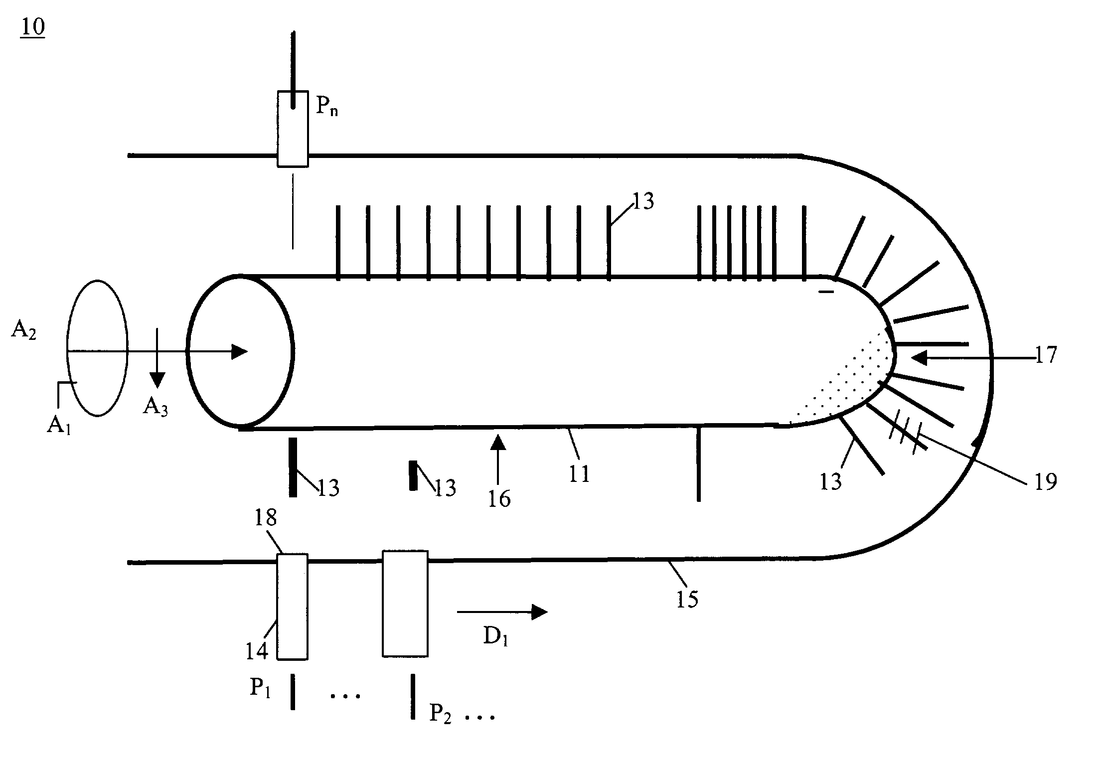
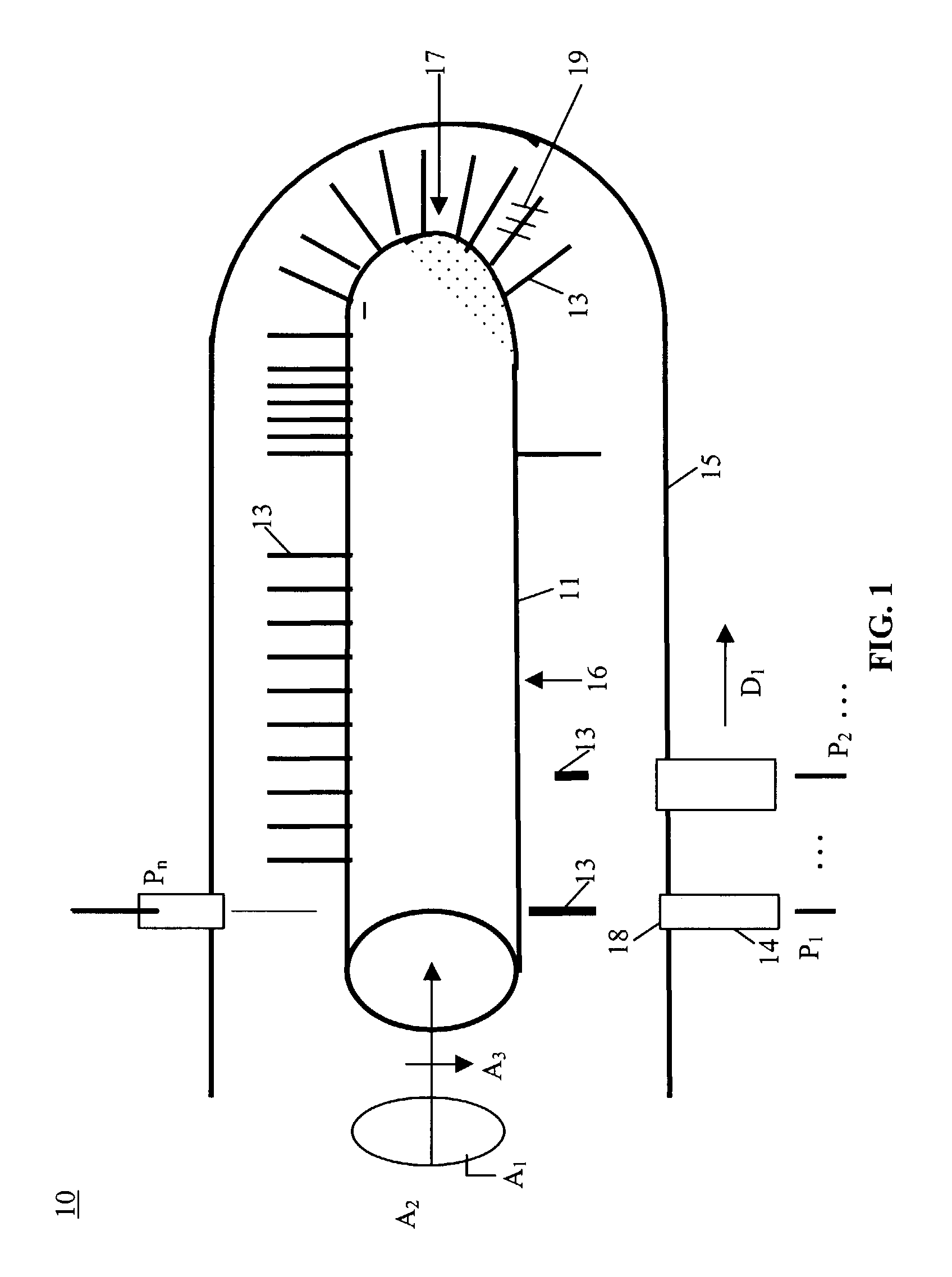
[0020]FIG. 1 is a schematic diagram of a system for manufacturing a cosmetic applicator 10 in accordance with the teachings of the present invention. Adhesive film 11 is applied to one or more portions of stem 12. Adhesive film 11 is applied to portions of stem 12 selected as portions to which flocking bristles 13 can be attached. For example, adhesive film 11 can be applied by dipping or spraying to form a substantially uniform film based on the surface tension, viscosity, additives of the adhesive film. Suitable adhesives include polymeric adhesive materials.

[0021]Flocking dispenser 14 dispenses flocking bristles 13 towards stem 12. Flocking dispenser 14 can move forward and backwards al...


PUM

PropertyMeasurementUnit
sizeaaaaaaaaaa
adhesiveaaaaaaaaaa
shapeaaaaaaaaaa

Abstract

The present invention relates to a method and system of manufacturing a cosmetic applicator in which a predetermined pattern of flocking bristles are dispensed toward the applicator and are adhered to the applicator by an adhesive. The flocking bristles can be dispensed using a flocking dispenser. The flocking dispenser is moveable in a longitudinal direction forward and backward along the sides and tip of the applicator. During or after movement of the flocking dispenser, the applicator can be rotated around its longitudinal axis. The movement of the flocking dispenser and rotation of the applicator can be controlled to provide the desired pattern of flocking bristles. The density of distribution of the flocking bristles can be controlled by varying the speed of movement and rotation of the applicator and the amount of flocking bristles which are dispensed from the flocking dispenser. For example, a high density of flocking bristles can be applied to extend radially from the tip. The flocking bristles can include one or more types of bristles which differ by one or more of material, cross section, shape, length, diameter or composition.

Description

[0001]This application claims priority of Provisional Application No. 60 / 362,274, filed Mar. 6, 2002, entitled “Mascara Applicator,” the contents of which are incorporated in its entirety into this application.BACKGROUND OF THE INVENTION[0002]1. Field of the Invention[0003]The invention relates to a cosmetic applicator and a method and system of manufacturing the applicator in which a plurality of bristles can be attached to the applicator in a predetermined distribution using a flocking dispenser and movement controlled system.[0004]2. Description of the Related Art[0005]Conventional applicators for mascara eyebrow, eyelashes lotion or the like comprise a handle and at the free end of which is applicator. In general, the core of the brush is formed by two branches of a metal wire twisted into a helix. The bristles extend in the turns formed by the twisted branches. The tips of the bristles define a generally cylindrical outer surface having two diametrically opposed channels and ap...

Claims


Application Information

Patent Timeline
Patent Type & Authority Patents(United States)
IPC IPC(8): A46B3/02A46D3/00
CPCA46B3/02A46D3/00A46B2200/1053
Inventor KEPKA, STANLEY W.
Owner KEPKA STANLEY W
Why Eureka
Try Eureka