Method and system for controlling ion distribution during plating of a metal on a workpiece surface

a technology of ion distribution and workpiece surface, which is applied in the direction of cell components, manufacturing tools, electric circuits, etc., can solve the problems of increasing complexity, chemically mechanically polishing a patterned surface provided on a large-diameter substrate, and a difficult task for process engineers

Active Publication Date: 2005-12-13
FULLBRITE CAPITAL PARTNERS
View PDF5 Cites 13 Cited by
  • Summary
  • Abstract
  • Description
  • Claims
  • Application Information

AI Technical Summary

Problems solved by technology

Although electroplating of copper is a well-established technique, reliably depositing copper over large-diameter wafers, having a patterned surface including trenches and vias, is a challenging task for process engineers.
The situation gains even more in complexity as the diameters of the substrates tend to increase.
It turns out, however, that chemically mechanically polishing a patterned surface provided on a large-diameter substrate is per se an extremely complex process.
The problems involved in the CMP process are even exacerbated when the thickness of the metal layer to be removed varies across the surface of the substrate.
Typically, the CMP process may exhibit a certain intrinsic non-uniformity, depending on the type of materials to be removed and the specific process conditions, and the like, and the combined non-uniformity of the metal deposition process and the CMP process may result in unacceptable variations of the finally obtained metal trenches and vias.
Although the adaptation of the diffuser element 111 to given polishing requirements allows to significantly improve the uniformity of the finally obtained metal layer, the process described above is cumbersome, in that it requires dismantling the diffuser element 111 and reinstalling after modification of the diffuser element.
This is especially disadvantageous, when a plurality of test runs has to be carried out to find the appropriate pattern configuration for the diffuser element 111.

Method used


Image

  • Method and system for controlling ion distribution during plating of a metal on a workpiece surface
  • Method and system for controlling ion distribution during plating of a metal on a workpiece surface
  • Method and system for controlling ion distribution during plating of a metal on a workpiece surface

Examples


Embodiment Construction

[0031]While the present invention is described with reference to the embodiments as illustrated in the following detailed description, as well as in the drawings, it should be understood that the following detailed description, as well as the drawings, are not intended to limit the present invention to the particular illustrative embodiments disclosed, but rather the described illustrative embodiments merely exemplify the various aspects of the present invention, the scope of which is defined by the appended claims.

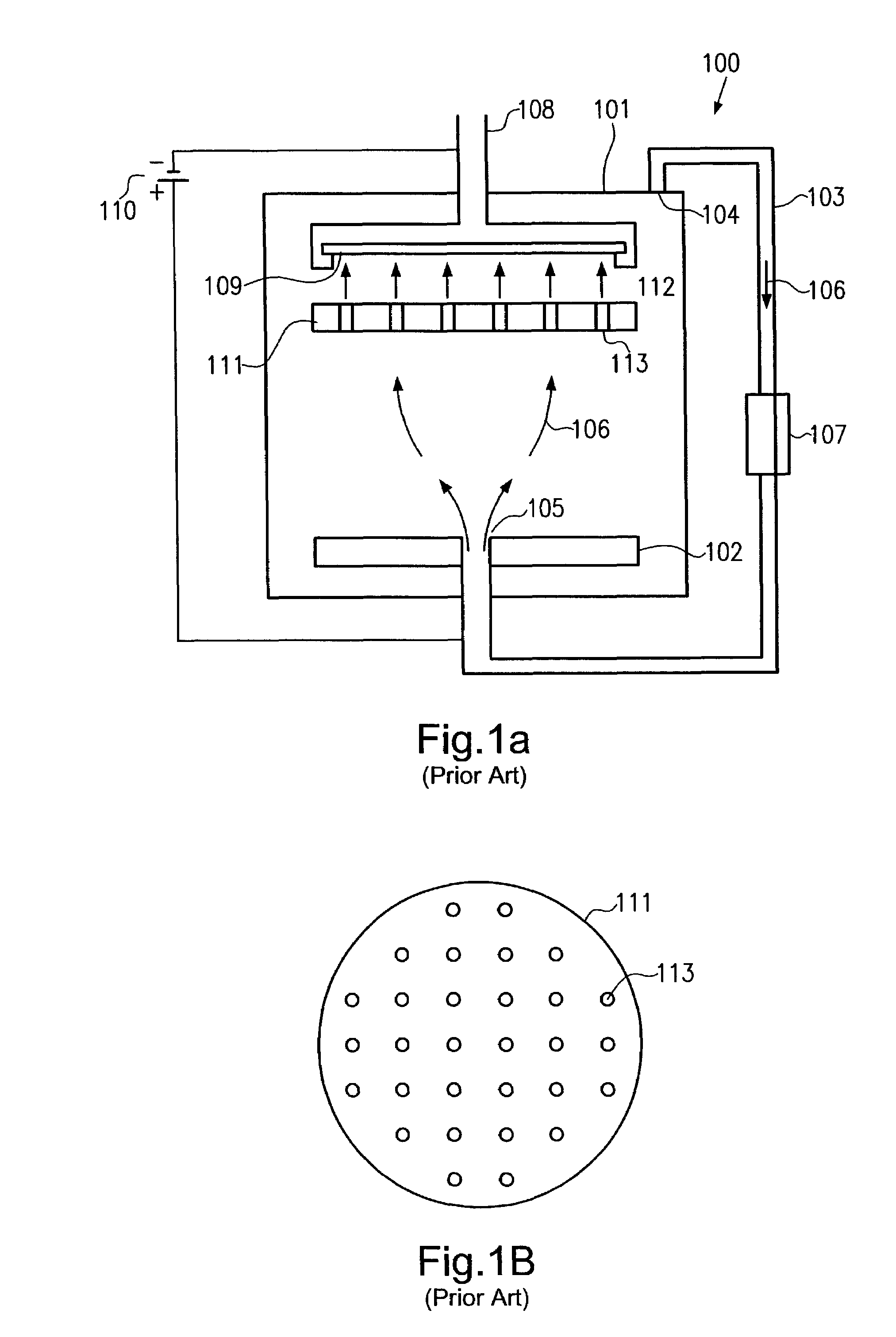
[0032]It is further to be noted that the detailed description will refer to electroplating of copper on substrates, such as those typically used in semiconductor fabrication. It will be readily appreciated, however, that the present invention is applicable to any plating process, either electroless or with an externally impressed current (electroplating), of any types of substrates. Moreover, although the description will refer to a fountain type plating reactor, for exam...


PUM

PropertyMeasurementUnit
thicknessaaaaaaaaaa
widthaaaaaaaaaa
thicknessaaaaaaaaaa

Abstract

The flow of electrolyte and / or of ions is controlled by a diffuser element provided in a plating reactor, wherein, in one embodiment, the diffuser element comprises a mechanical adjustment mechanism to adjust the effective size of passages of the diffuser element. In another embodiment, the diffuser element comprises at least two patterns of passages that are movable relatively to each other so as to adjust an overlap and thus an effective size of the corresponding passages. Moreover, the path of ions within the plating reactor may be controlled by an electromagnetically driven diffuser element so that a required thickness profile on the workpiece surface may be obtained.

Description

[0001]1. Field of the Present Invention[0002]The present invention relates to depositing a metal on a workpiece surface, using a reactor for electroplating or electroless plating, and, more particularly, to the distribution of electrolyte flow and / or ion flow across the workpiece surface.[0003]2. Description of the Prior Art[0004]In many technical fields, the deposition of metal layers on a workpiece surface is a frequently employed technique. For efficiently depositing relatively thick metal layers on a workpiece surface, plating, in the form of electroplating or electroless plating, has proven to be a viable and cost-effective method and, thus, plating has become an attractive deposition method in the semiconductor industry.[0005]Nowadays, copper has become a preferred candidate in forming metallization layers in sophisticated integrated circuits due to the superior characteristics of copper and copper alloys in view of conductivity and resistance to electromigration compared to, ...

Claims


Application Information

Patent Timeline
Patent Type & Authority Patents(United States)
IPC IPC(8): C25D5/00C25D5/02C25D7/12C25D17/00
CPCC25D5/02C25D17/008C25D7/123C25D17/001C25D5/006Y10S204/07C25D5/007
Inventor BONKASS, MATTHIASPREUSSE, AXEL
Owner FULLBRITE CAPITAL PARTNERS
Why Eureka
Try Eureka