
Method and apparatus for three-dimensional surface scanning and measurement of a moving object

Inactive Publication Date: 2005-12-13
WANG BU CHIN
View PDF5 Cites 56 Cited by
  • Summary
  • Abstract
  • Description
  • Claims
  • Application Information

AI Technical Summary

Benefits of technology

[0010]An advantage of the present invention is that a unique set of equations and calibration techniques are used to compute the surface coordinates of a 3D object. The equations are independent from the focus length of the image sensor, thereby eliminating the sensitivity of the accuracy of the computation due to any inaccuracy in measurement of the focus length inherent in most existing scanners. The calibration techniques make the coordinate computation insensitive to the distance from sensor to the coordinate origin.
[0011]Another advantage of the present invention is that a second scan module is used to scan the 3D object under the same planar light, thereby increasing the area available to scan for image data, which of course improves the accuracy of the measurement.
[0012]A still further advantage of the present invention is that it merges two sets of independently measured slice based coordinate data and then forms the complete 3D composite data. This method reduces alignment error and provides more accurate coordinates of the 3D object surface.

Problems solved by technology

Since the focus length is small relative to the distance from the sensor to the object, the measured value of the focus length significantly affects the accuracy of the computation.
However, the current art devices available on the market are limited, typically in one of two ways: (1) The scan module itself is typically a stand alone item, such as the LD100*-*F and the LD250*-*F Laser Distance Meters manufactured by the Toshiba Corporation, and the device disclosed in “A Laser Range Scanner Designed for Minimum Calibration Complexity”, by James Davis and Xing Chen in the 2001 IEEE Proceedings of the 3rd International Conference on Digital Imaging and Modeling.

Method used


Image

  • Method and apparatus for three-dimensional surface scanning and measurement of a moving object
  • Method and apparatus for three-dimensional surface scanning and measurement of a moving object
  • Method and apparatus for three-dimensional surface scanning and measurement of a moving object

Examples


Embodiment Construction

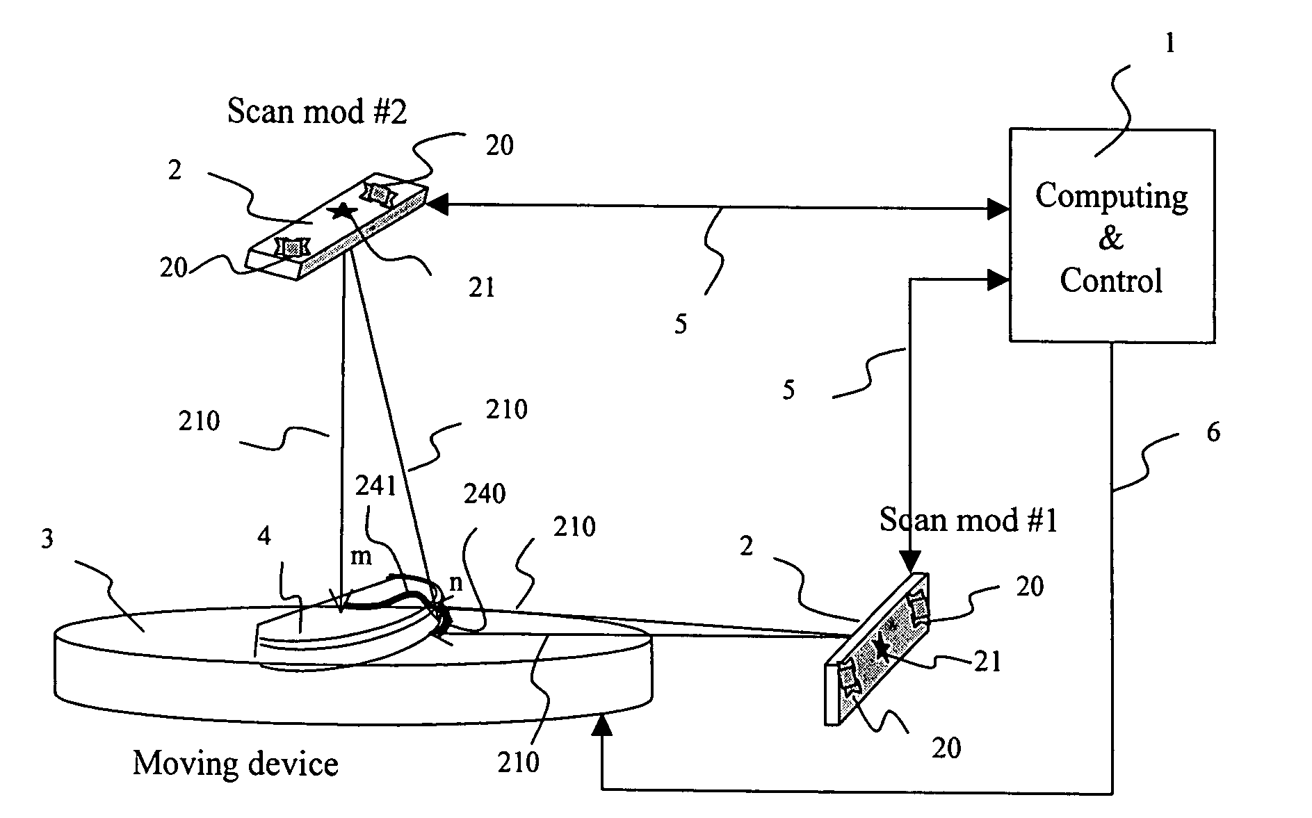
[0034]The present invention is a three dimensional (3D) scanning technique based on a non-contact device, the scan module. The scan module utilizes a line light source and an image sensor to scan the surface of a physical object. A set of mathematical equations are used to compute the coordinates defining the scanned object's surface. Multiple aligned scan modules are used, with the data from the multiple scan modules being merged into a single coordinate map.

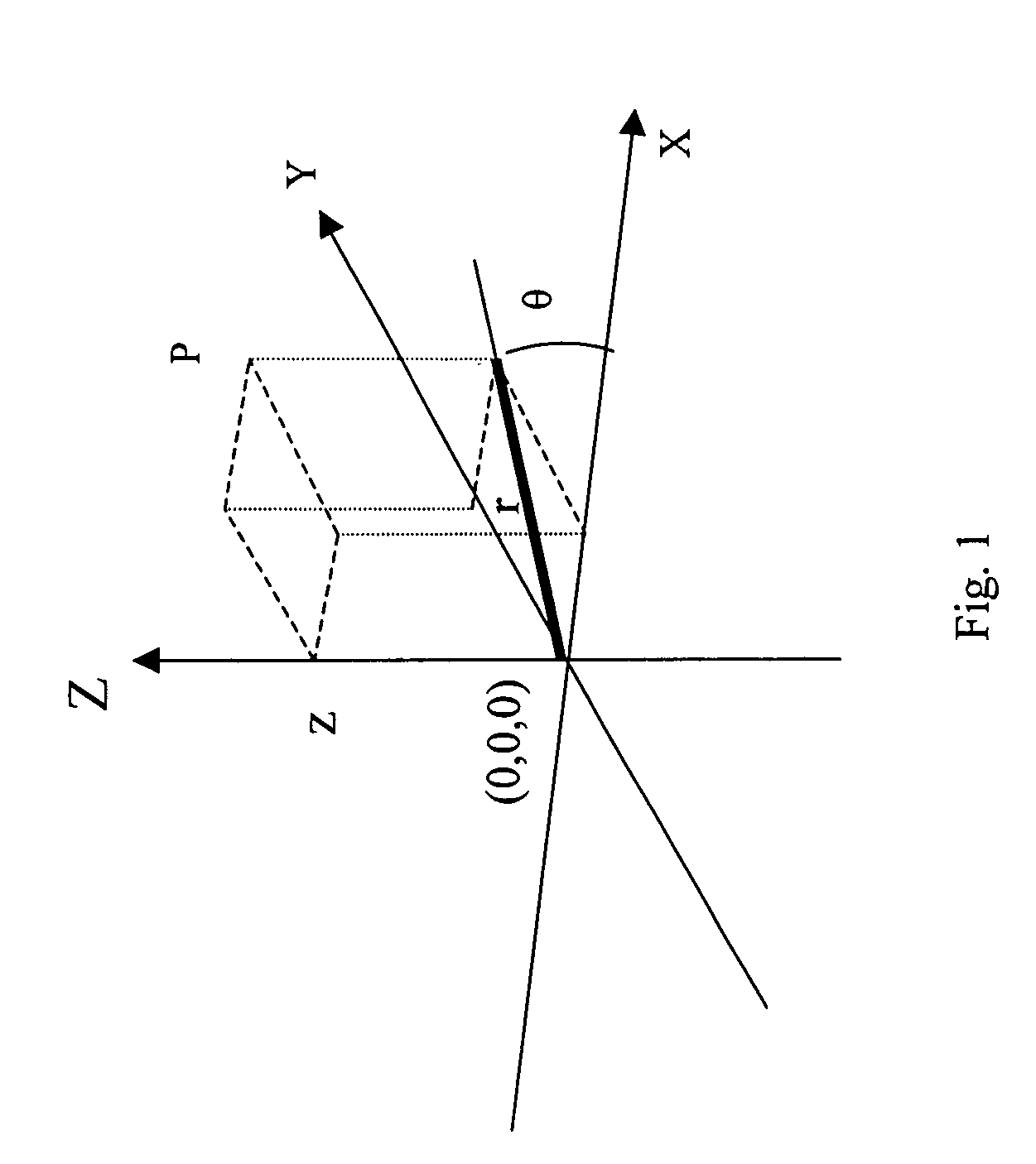
[0035]The position of a point P can be represented by either rectangular coordinates (x, y, z), or by cylindrical coordinates (r, θ, z). FIG. 1 displays the relationship of these two systems.

x=r*cos θ

y=r*sin θ[0036]z is the same in both systems

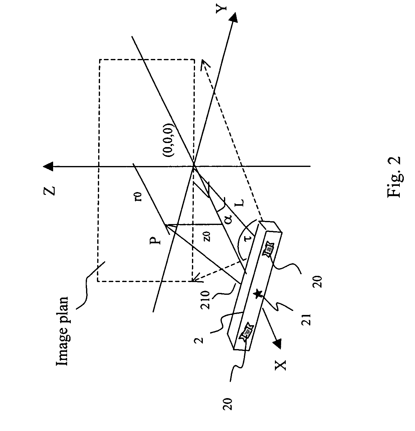
[0037]There exist many light based techniques to measure the coordinates defining the surface of an object. FIG. 2 illustrates the measuring system of the present invention comprising a scan module 2 which includes a light source 21, an image sensor 20, a projected light stripe 210 (that ...


PUM


Abstract

An apparatus and method to scan and collect data relative to the position of a moving object. The method includes the calibration, equations, and algorithm needed to compute the surface coordinates of an object. The preferred embodiment of the apparatus includes two light sources and four area array image sensors, one moving device, and one computing device. The device scans the object, generates data, computes the position, and provides a complete measure of the 3D surface coordinates of an object. The methodology includes calibration of a known pattern to the area array image sensor, equations to map the physical points to the image sensor, algorithms to determine a best estimate of the coordinates of occluded points, and techniques to merge the computed coordinates from different sections of the object.

Description

[0001]This application claims the benefit of U.S. Provisional Application No. 60 / 389,169, filed Jun. 17, 2002.BACKGROUND OF THE INVENTION[0002]1. Field of the Invention[0003]The present invention relates to a method and apparatus for the measurement of three-dimensional surface coordinates of an object with controlled movement along a slit line. More particularly the present invention provides an improved method of computing the coordinates of a line-scan based object.[0004]2. Description of the Prior Art[0005]The prior art has several examples of devices that utilize a light stripe and image sensors to obtain the coordinates of a subject object. The conventional triangulation computation is a cost effective method. Several references disclose methodologies using triangulation to compute the coordinates of an object. The triangulation methods become cost effective and highly precise when implemented with a PC. One example of such a prior art reference is the “Method and Apparatus fo...

Claims


Application Information

Patent Timeline
IPC IPC(8): A61C9/00A61C13/00G01B11/25G01N21/86G01V8/00
CPCA61C13/0004G01B11/2522A61C9/004A61C9/0053A61C9/0093G16H20/40
Inventor WANG, BU-CHIN
Owner WANG BU CHIN
Learn More