Dynamo-electric machine having a rotor with first and second axially or rotationally displaceable field magnets

a dynamo-electric machine and rotor technology, applied in the direction of magnetic circuit rotating parts, electric motor propulsion transmission, magnetic circuit shape/form/construction, etc., can solve the problems of reduced heat generation efficiency, difficult operation in high-speed range, complex structure of spring and governor, etc., to achieve the effect of weakening magnetic flux and simple structur

Inactive Publication Date: 2005-12-13
HITACHI LTD
View PDF27 Cites 38 Cited by
  • Summary
  • Abstract
  • Description
  • Claims
  • Application Information

AI Technical Summary

Benefits of technology

[0007]An object of the present invention is to provide a dynamo-electric machine, in which the fiel

Problems solved by technology

Accordingly, high torque can be obtained in a low-speed range, but operation in a high-speed range is difficult because the variable range of rotating speed is narrow.
The method of widening the high speed operation range using the field weakening control tec

Method used


Image

  • Dynamo-electric machine having a rotor with first and second axially or rotationally displaceable field magnets
  • Dynamo-electric machine having a rotor with first and second axially or rotationally displaceable field magnets
  • Dynamo-electric machine having a rotor with first and second axially or rotationally displaceable field magnets

Examples


Embodiment Construction

[0033]Embodiments of the present invention will be explained.

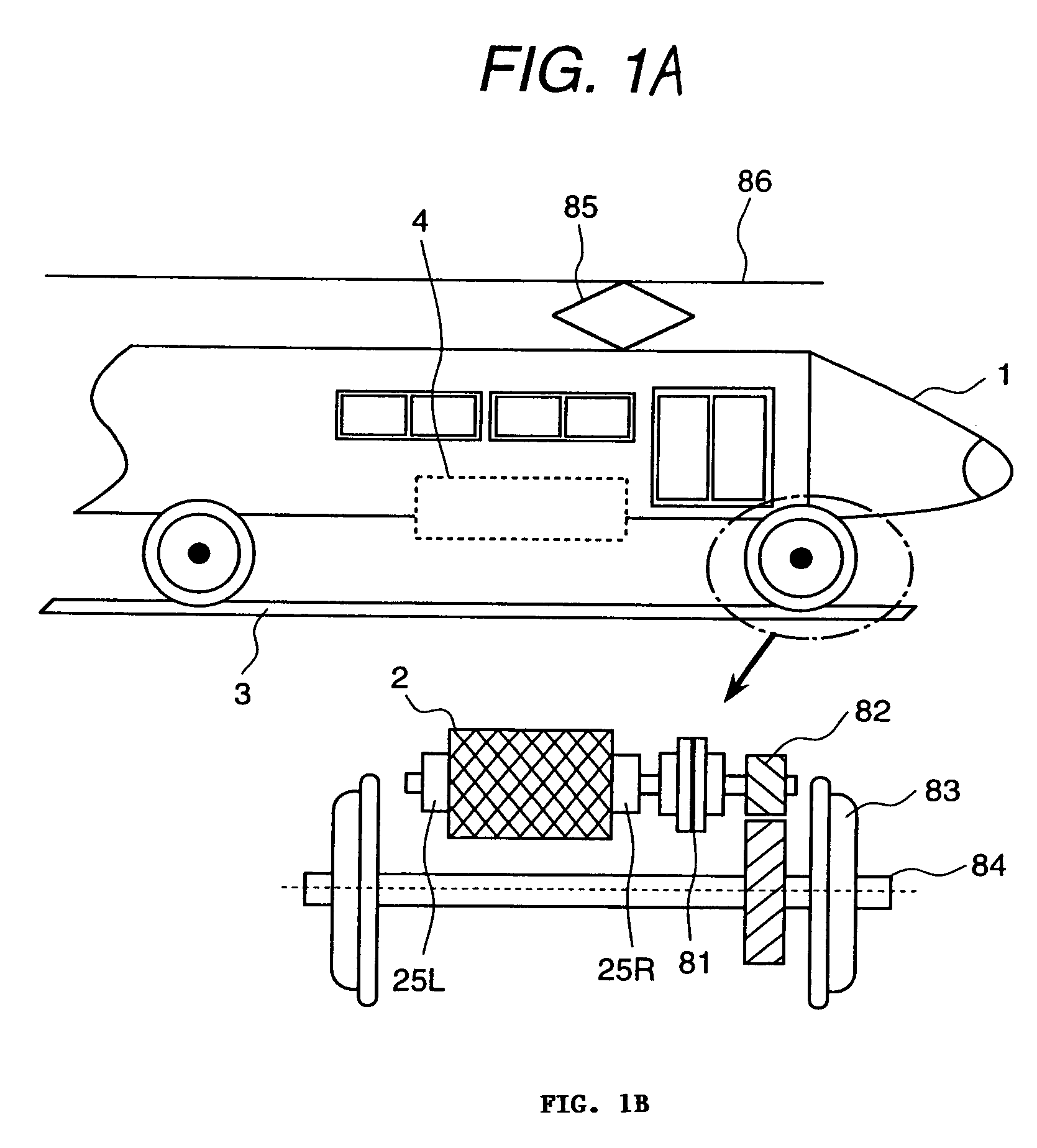
[0034]FIG. 1 shows the arrangement layout of a permanent magnet type synchronous dynamo-electric machine according to an embodiment of the present invention.

[0035]There are various transport systems which use the dynamo-electric machine as a power source. FIG. 1 shows the embodiment of a railway rolling stock system as one example of the transport system.

[0036]The railway rolling stock system shown in FIG. 1 has electric car 1, dynamo-electric machine 2, wheel 83 installed directly or indirectly on the dynamo-electric machine 2, power conversion machine 4 for controlling the electric power of dynamo-electric machine 2, and current collector 85.

[0037]Here, the electric car means the rolling stock which uses electricity as the power. Further, in the transport system including the rolling stock system, the electric car means a truck in a broad sense.

[0038]Further, the current collector is a device for taking the electric powe...


PUM


Abstract

A dynamo-electric machine has a stator with a primary winding and a rotor with a field magnet and a shaft. the field magnet includes a first field magnet having diferent polarity magnetic poles sequentially arranged in a rotation direction and a second field magnet having diferent polarity magnetic poles sequentially arranged in a rotation direction. The machine further has a mechanism for shifting the first and the second field magnets in axial and rotation directions.

Description

BACKGROUND OF THE INVENTION[0001]The present invention relates to a dynamo-electric machine which uses a permanent magnet for field system, and particularly to a method and a dynamo-electric machine for performing the drive and regeneration in a carrier system or transport system.[0002]In a permanent magnet field type dynamo-electric machine of the prior art, an induced electromotive force E is determined by a constant magnetic flux Φ generated by a permanent magnet arranged in a rotor and a rotating angular speed ω of the dynamo-electric machine. That is, when the rotating angular speed ω (rotating speed) of the dynamo-electric machine is increased, the induced electromotive force is proportionally increased.[0003]Accordingly, high torque can be obtained in a low-speed range, but operation in a high-speed range is difficult because the variable range of rotating speed is narrow. Therefore, it may be considered that the high-speed operation range is widened using a field weakening c...

Claims


Application Information

Patent Timeline
IPC IPC(8): B61C9/48B61F3/04B61F3/16H02K1/22H02K1/27H02K1/28H02K16/02H02K21/00H02K21/14
CPCB61C9/48B61F3/04B61F3/16H02K16/02H02K21/029Y02T30/00
Inventor JOONG, KIM HOUNGUEDA, SHIGETA
Owner HITACHI LTD
Why Eureka
Try Eureka