
Electric motor

a technology of electric motors and motors, applied in the direction of dynamo-electric components, coupling for high frequency, electromagnetic interference suppression, etc., can solve the problems of difficult arrangement of a member such as a condenser, inability to secure a sufficient space between the power feeding terminal in the end portion and the rotation axis, etc., to reduce the space for placing the noise preventing element, reduce the manufacturing cost, and reduce the effect of spa

Active Publication Date: 2005-12-13
MITSUBA CORP
View PDF6 Cites 18 Cited by
  • Summary
  • Abstract
  • Description
  • Claims
  • Application Information

AI Technical Summary

Benefits of technology

The present invention provides an electric motor with an armature and a brush holder. The brush holder has a first and second power feeding terminals that are fixed to the brush holder and connected to the armature. The motor housing has a first and second power feeding terminal fixed to it. The brush holder has a flat shape and the power feeding terminals are fixed to the brush holder. The first and second power feeding terminals are arranged side by side in the axial direction of the rotation axis. The invention also provides a noise absorbing element connected to the power feeding terminals and a grounding member that connects the conductive member to the motor housing. The invention improves the layout property of the motor and prevents the noise absorbing element from moving to the side of the rotation axis. The invention also makes it easier to assemble the electric motor and improves its reliability in operation.

Problems solved by technology

However, in the electric motor as mentioned above, since the respective power feeding terminals are formed in a flat shape, and are arranged in such a manner as to face the flat portions thereof to each other, it is impossible to secure a sufficient space between the power feeding terminal in the end portion and the rotation axis.
Therefore, for example, it is hard to arrange a member such as a condenser or the like which is connected to a portion between the respective power feeding terminals and corresponds to a noise absorbing element for absorbing an electric noise generated by the brush portion, on the compact brush holder.

Method used


Image

  • Electric motor
  • Electric motor
  • Electric motor

Examples


Embodiment Construction

[0049]A description will be in detail given below of an embodiment in accordance with the present invention with reference to the accompanying drawings.

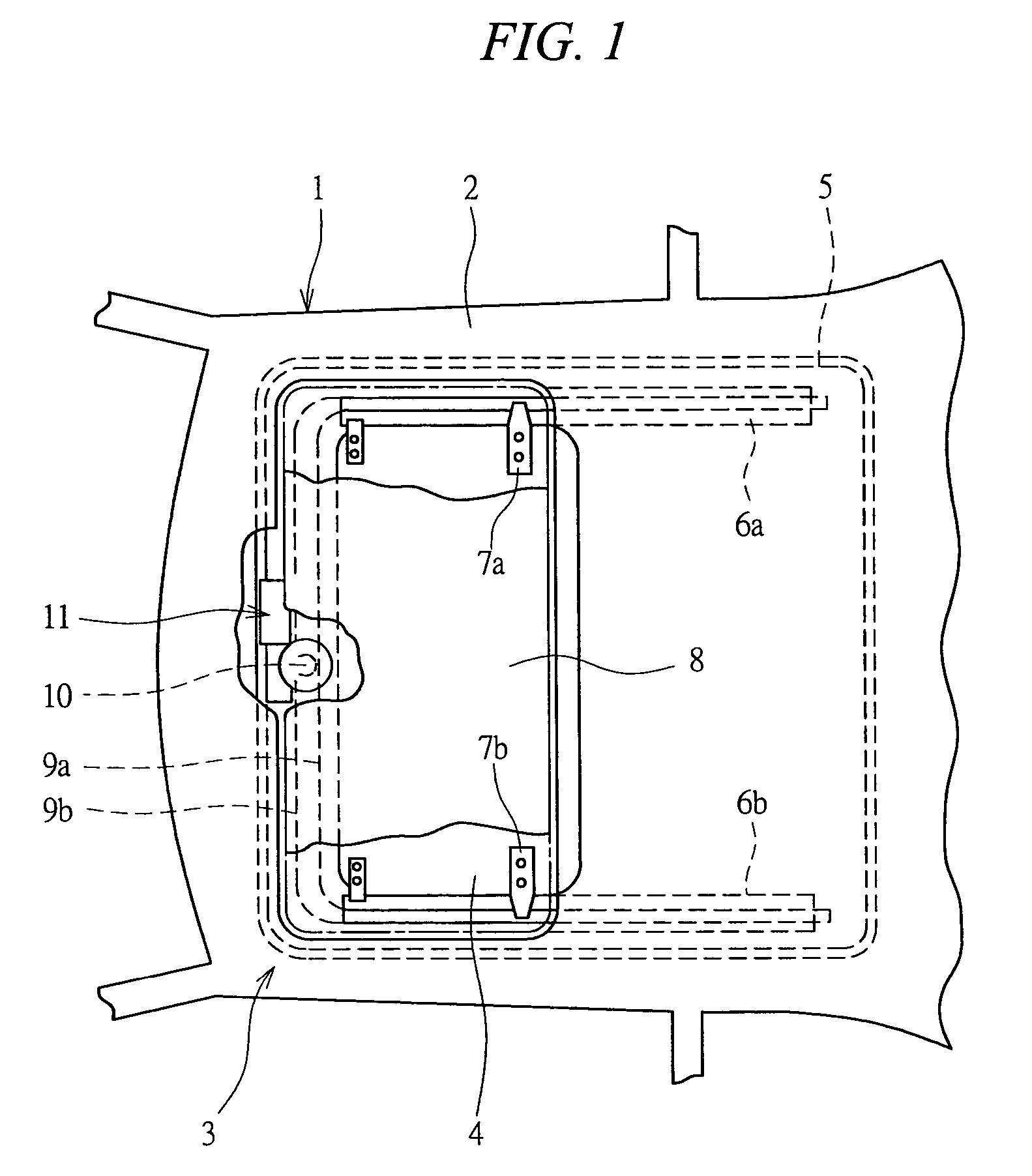
[0050]As shown in FIG. 1, a sunroof apparatus 3 is provided in a roof 2 of a vehicle 1. The sunroof apparatus 3 has a mounting frame 5 which is fixed to a position in the periphery of an opening portion 4 formed in the roof 2, and two guide rails 6a and 6b extending in a back and forth direction of the vehicle are fixed to the mounting frame 5. Shoes 7a and 7b are respectively attached to the guide rails 6a and 6b so as to freely move along the guide rails 6a and 6b, and a roof panel 8 is fixed to the shoes 7a and 7b. Then, the roof panel 8 is structured such as to be guided by the guide rails 6a and 6b integrally with the shoes 7a and 7b so as to be freely opened and closed in the back and forth direction of the vehicle.

[0051]Respective one ends of driving cables 9a and 9b with gears are connected to the shoes 7a and 7b. These drivi...


PUM


Abstract

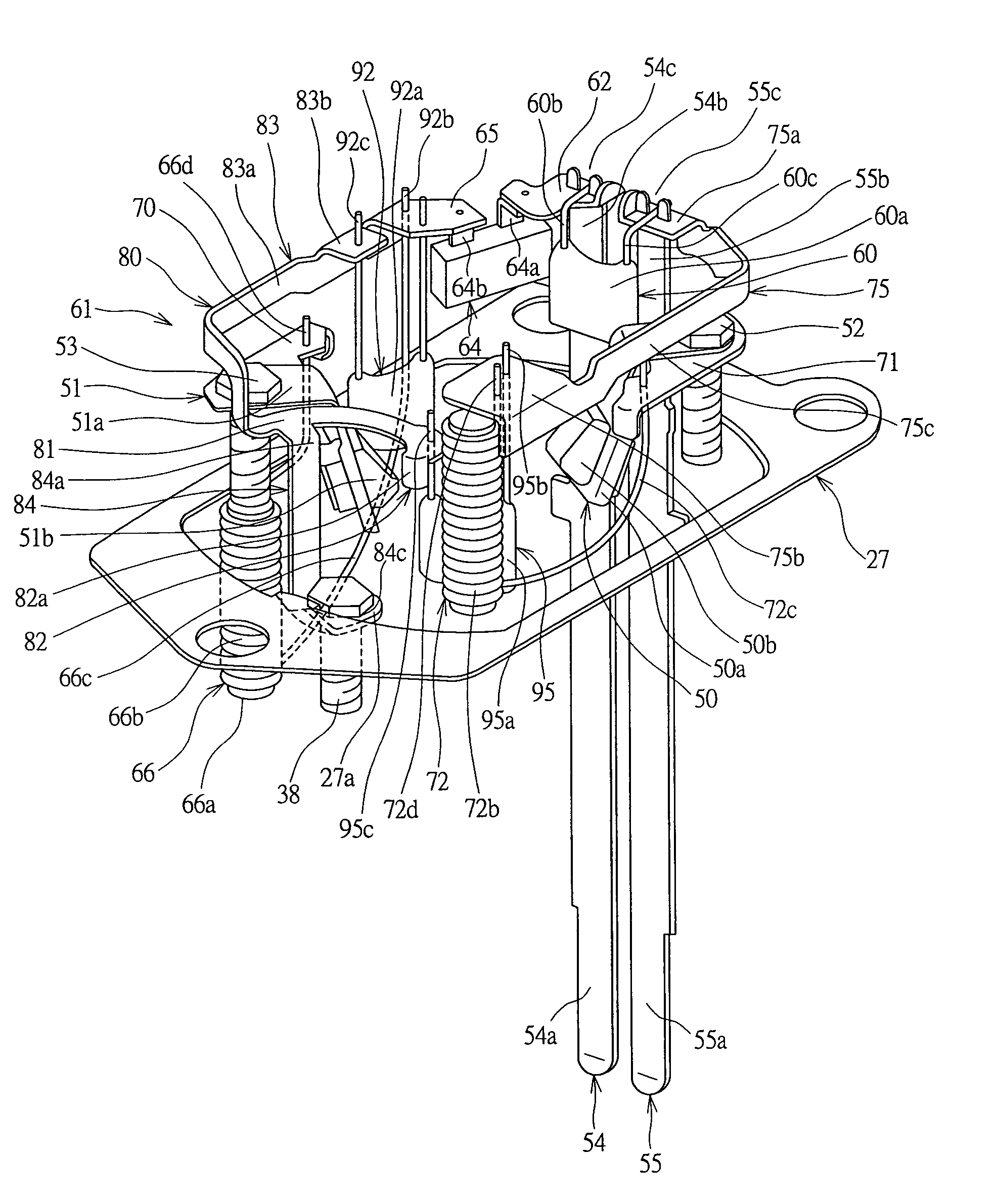
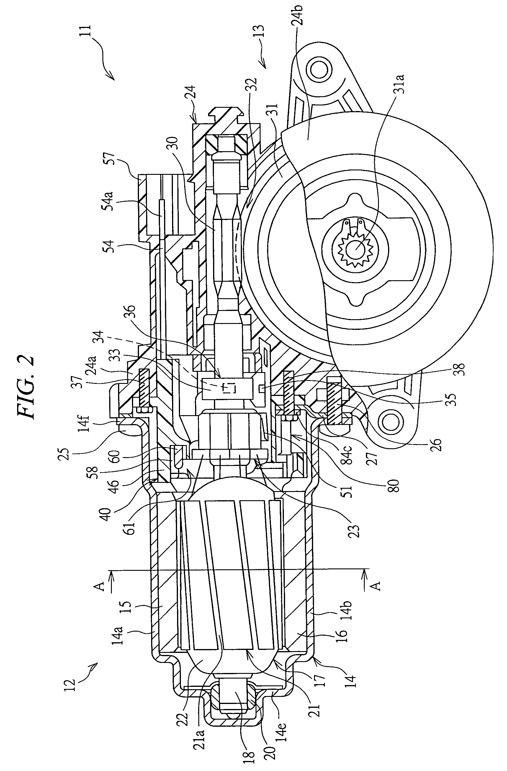
An object of the invention is to improve a layout property of members arranged on the brush holder. Power feeding terminals are formed in a flat shape extending in an axial direction of an armature shaft, and the power feeding terminal is arranged side by side in a width direction with respect to the power feeding terminal in one end portion of a brush holder. A condenser is provided between the power feeding terminals and the armature shaft. Further, a power supply circuit for electrically connecting the power feeding terminals to a leaf spring brush is electrically connected to a motor housing via a grounding stay, and a choke coil for reducing a noise generated in the power supply circuit is arranged so as to be lapped over a screw member fixing the leaf spring brush to the brush holder in the axial direction of the armature shaft.

Description

[0001]This application is entitled to the benefit of and incorporates by reference essential subject matter disclosed in Japanese Patent Application No. 2002-209525 filed on Jul. 18, 2002.TECHNICAL FIELD OF THE INVENTION[0002]The present invention relates to an electric motor, and more particularly to a structure of a power feeding terminal connected to a power source.BACKGROUND OF THE INVENTION[0003]In conventional, an electric motor has been used as a driving source of a sunroof apparatus and a power window apparatus which are provided in a vehicle. The electric motor mentioned above has a motor housing in which two permanent magnets are fixed to an inner peripheral surface in such a manner as to face different magnetic poles to each other, and an armature which is rotatably received within the motor housing. The armature has a plurality of armature coils, and the armature coils are electrically connected to a commutator fixed to a rotation axis of the armature, respectively. The ...

Claims


Application Information

Patent Timeline
Patent Type & Authority Patents(United States)
IPC IPC(8): H01R13/719H01R39/38H02K5/14H02K5/22H02K11/00H02K11/02H02K13/00
CPCH01R39/383H02K5/148H02K5/225H02K11/0089H02K11/026H01R13/719H02K11/40
Inventor SAKAI, HIROSHIOTA, MASAYUKIISO, YUKIYOSHIOCHIAI, TAKAO
Owner MITSUBA CORP
Learn More