Variable speed drive with a synchronous electric motor

a synchronous electric motor and variable speed technology, applied in the direction of motor/generator/converter stopper, electronic commutator, dynamo-electric converter control, etc., can solve the problems of increasing motor heating and acoustic noise, increasing costs, and producing significant torque ripples, so as to reduce the resolution of the required rotor position sensor, smooth transition, and high speed

Inactive Publication Date: 2005-12-13
NUGEN MOBILITY
View PDF5 Cites 10 Cited by
  • Summary
  • Abstract
  • Description
  • Claims
  • Application Information

AI Technical Summary

Benefits of technology

[0007]This invention relates to a variable speed drive having a synchronous AC electric motor. In the disclosed embodiment, a variable speed drive operates in three modes: a first predetermined mode, in which a function (e.g., trapezoidal current waveform) controls operation at low motor speeds; a transitional mode, in which a transition function is applied to anticipate transitions of the first function, thus causing a smoothing of transitions at higher speeds; and a second predetermined (e.g., sinusoidal or smoothly-varying current) waveform at high speeds. This allows for the reduction in required rotor position sensor resolution as compared to conventional synchronous variable speed drives, resulting in cost savings in the sensor device and associated wiring. Additionally, it is quieter and more efficient operation at high speed as compared to conventional trapezoidal-current / DC-brushless motor drives.

Problems solved by technology

A problem in connection with ordinary variable speed drives is that they either require high-resolution position measurement devices, or must utilize stepped current waveforms that increase motor heating and acoustical noise.
These stepped current waveforms, referred to as trapezoidal waveforms or “6-step” waveforms when applied to a three-phase motor, can also produce significant torque ripple.
Frequently this alignment is a manual operation, further increasing costs.
This type of algorithm is not suited for the majority of electric motors on the market, as they lack the requisite rotor features.
This approach has a critical limitation, however, in that it cannot be used at arbitrarily low speeds.

Method used


Image

  • Variable speed drive with a synchronous electric motor
  • Variable speed drive with a synchronous electric motor
  • Variable speed drive with a synchronous electric motor

Examples


Embodiment Construction

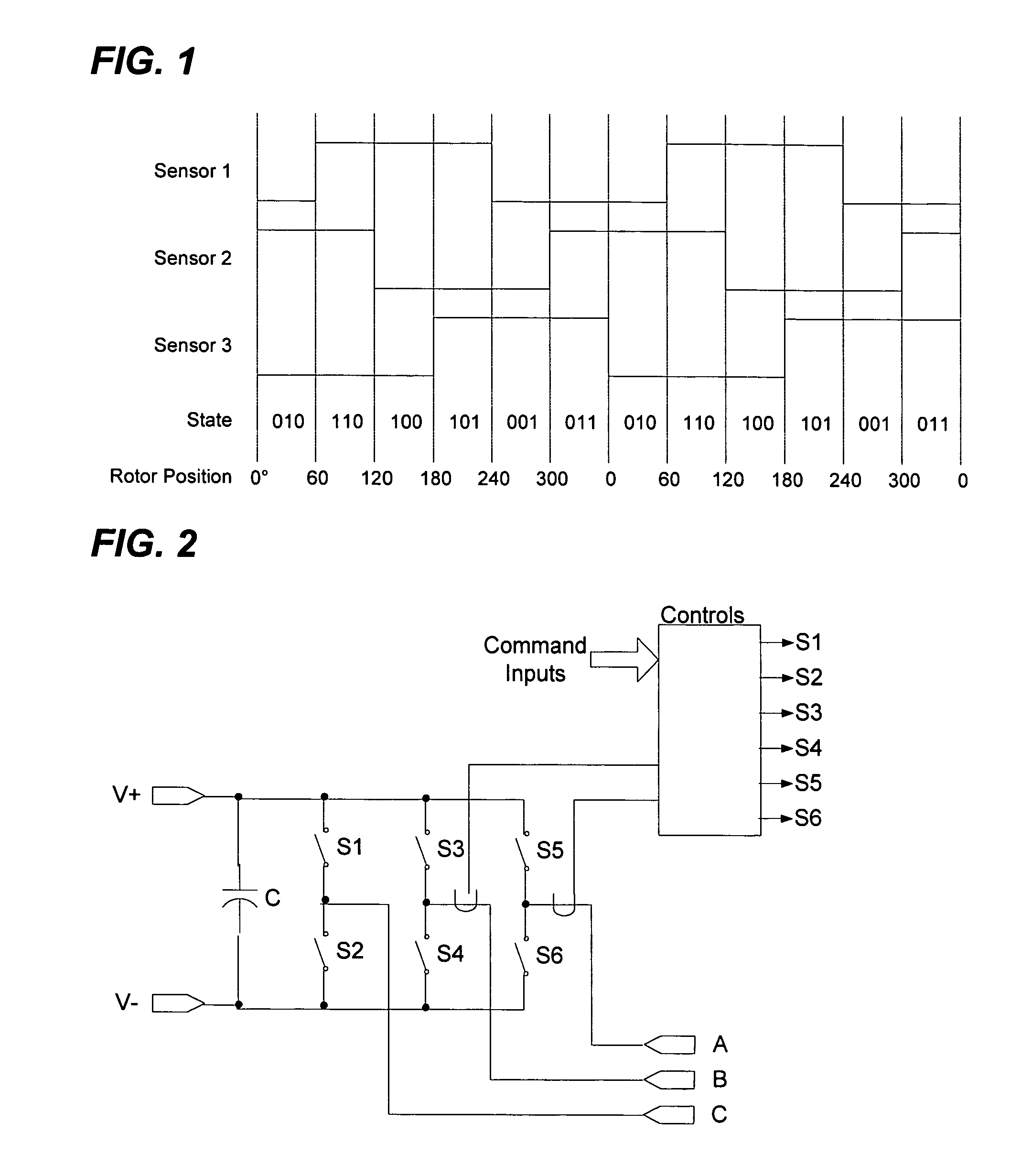
[0020]The present invention comprises a polyphase electric motor equipped with plural binary output position sensors, configured such that each sensor asserts its output over a fixed angular range. Common sensors used for this purpose are Hall-effect devices exposed to the rotor's magnetic field and optical encoders. The ranges over which the sensors assert their outputs are by design or are determined during a motor calibration procedure. When multiple sensors are used, their ranges partially overlap, and the rotor position can be known to be within a reduced angular range based on the state of the sensors. For three phase synchronous motors it is common to use three sensors, arranged so that one of the three sensors changes state every 60°. With such an arrangement the rotor can always be known to be within a 60° range. This is illustrated in FIG. 1.

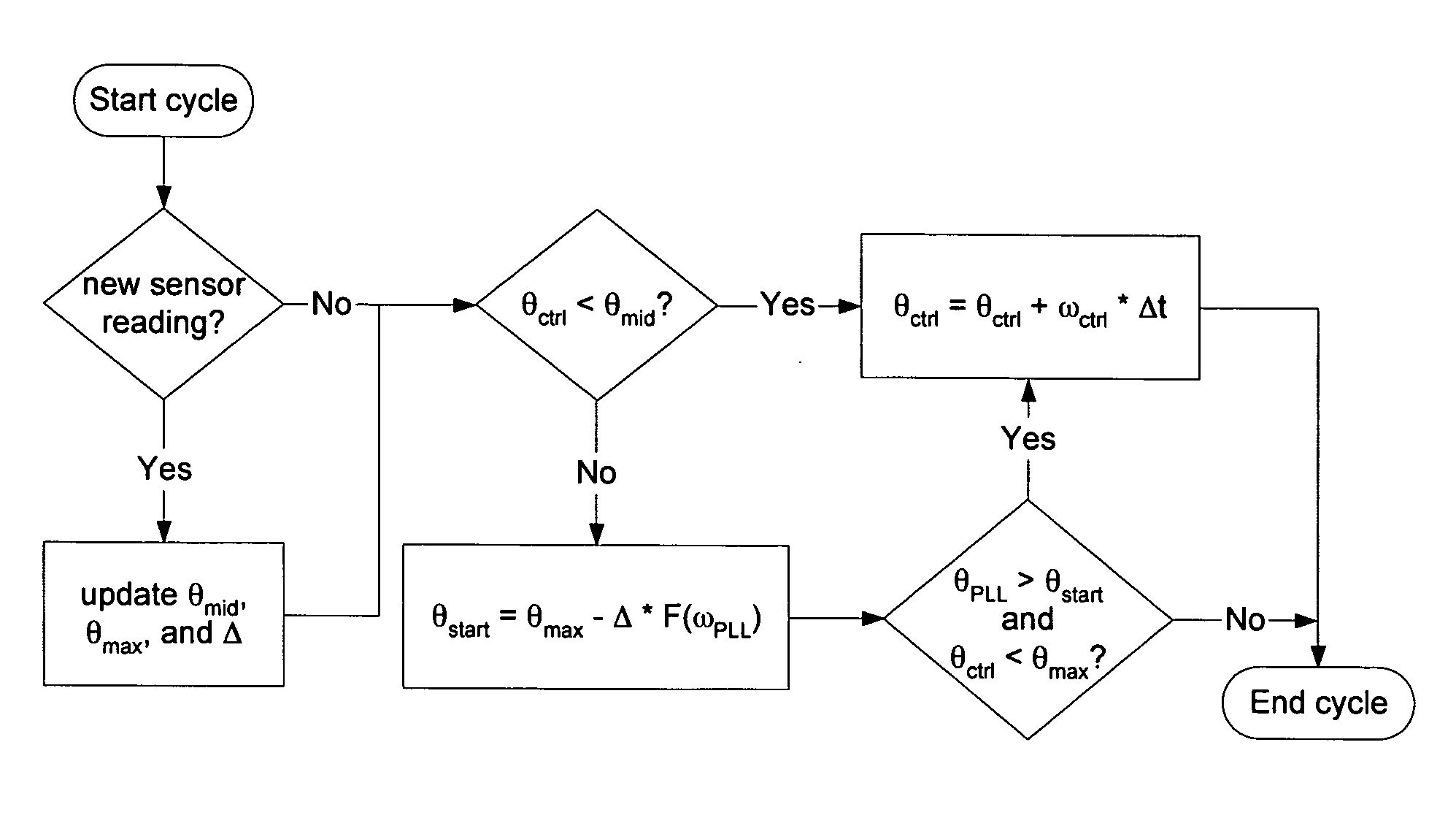
[0021]A second aspect of the preferred embodiment of the invention is a polyphase inverter. This inverter includes control means to p...


PUM


Abstract

This invention relates to a variable speed drive with synchronous AC motor. In the disclosed embodiment, a variable speed drive operates in three modes: a first predetermined mode, in which a function (e.g., trapezoidal current waveform) controls operation at low motor speeds; a transitional mode, in which a transition function is applied to anticipate transitions of the first function, thus causing a smoothing of transitions at higher speeds; and a second predetermined (e.g., sinusoidal or smoothly-varying current) waveform at high speeds. This allows for the reduction in required rotor position sensor resolution as compared to conventional synchronous variable speed drives, resulting in cost savings in the sensor device and associated wiring. Additionally, it is quieter and more efficient operation at high speed as compared to conventional trapezoidal-current / DC-brushless motor drives.

Description

[0001]This application claims the benefit of application Ser. No. 60 / 450,767 filed Mar. 3, 2003.TECHNICAL FIELD[0002]Our invention generally relates to variable speed drives and, more specifically, the invention is related to the field of variable speed drives with synchronous electric motors.BACKGROUND OF THE INVENTION[0003]A problem in connection with ordinary variable speed drives is that they either require high-resolution position measurement devices, or must utilize stepped current waveforms that increase motor heating and acoustical noise. These stepped current waveforms, referred to as trapezoidal waveforms or “6-step” waveforms when applied to a three-phase motor, can also produce significant torque ripple. The use of high-resolution position measurement devices requires that the position measurement device be properly aligned relative to the stator and rotor poles. Frequently this alignment is a manual operation, further increasing costs.[0004]Algorithms for performing sen...

Claims


Application Information

Patent Timeline
Patent Type & Authority Patents(United States)
IPC IPC(8): B60K1/00H02P6/00H02P6/16H02P25/08
CPCB60K1/00H02P6/001H02P6/16H02P6/181H02P25/082H02P25/088H02P2209/07H02P6/34H02P25/0925H02P25/098
Inventor CRAIN, STEPHEN G.JERMAKIAN, JOEL B.
Owner NUGEN MOBILITY
Why Eureka
Try Eureka