Direct fuel injection type internal combustion engine

a technology of direct injection and internal combustion engine, which is applied in the direction of machines/engines, mechanical equipment, electric control, etc., can solve the problems of inability to make an inability to make an air-fuel mixture in time, and limited engine operation conditions that enable the formation of appropriate stratified air-fuel mixtures, etc., to achieve suppressors or suppressors, the effect of increasing the amount of unburned hydrocarbons in the exhaust gas

Inactive Publication Date: 2005-12-20
NISSAN MOTOR CO LTD
View PDF11 Cites 8 Cited by
  • Summary
  • Abstract
  • Description
  • Claims
  • Application Information

AI Technical Summary

Benefits of technology

[0007]Accordingly, it is an object of the present invention to provide a direct fuel injection type internal combustion engine that can easily produce an appropriate stratified air-fuel mixture.
[0018]In the present invention, the above-mentioned unique phenomenon revealed by the inventors is practically used. That is, by controlling the penetration force of the injected fuel in accordance with the operation condition of the engine, the fuel consumption characteristic and exhaust characteristic are improved.
[0019]In the present invention, under a lower engine speed, the fuel injection is carried out with a normal lower injection pressure so that with a lower penetration force, the atomized fuel from the injection nozzle produces a circulation of the atomized fuel in the cavity to produce an appropriate air-fuel mixture. While, under a higher engine speed, the fuel injection is carried out with a higher injection pressure so that with a higher penetration force, the atomized fuel from the injection nozzle produces an air-fuel mixture in a shorter time, the air-fuel mixture being substantially identical to the air-fuel mixture provided by the normal lower injection pressure with respect to the same ignition timing.
[0022]It is said that when a fuel injection is carried out under a lower temperature condition of the engine, that is, under a condition wherein the temperature of engine cooling water is relatively low, the amount of unburnt hydrocarbons (HC) in the exhaust gas is increased. However, in the present invention, provision of the above-mentioned second phase suppresses or at least minimizes such undesired phenomenon. That is, under the second phase, the moving speed of air at the leading end of the injected atomized fuel is higher than that of the fine fuel droplets and thus there a partial Weber's value is small thereby inducing a reduction of the fuel droplets collected on the peripheral wall surface of the cavity. Thus, increasing the fuel injection pressure under such lower temperature condition of the engine is an effective way to reduce exhaust emission.
[0024]As will be described in detail in the following, in accordance with the present invention, the penetration force of the injected atomized fuel is varied in accordance with the operation condition of the engine. With this measure, a stratified combustion of mixture can be carried out in an expanded operation range of the engine, and deterioration of emission characteristic at a higher engine speed can be suppressed or at least minimized.

Problems solved by technology

Thus, if for example the engine speed is increased, it tends to occur that formation of the air-fuel mixture is not made in time.
Accordingly, in fact, the operation condition of the engine that enables formation of an appropriate stratified air-fuel mixture is quite limited.

Method used


Image

  • Direct fuel injection type internal combustion engine
  • Direct fuel injection type internal combustion engine
  • Direct fuel injection type internal combustion engine

Examples


Embodiment Construction

[0037]In the following, the present invention will be described in detail with reference to the accompanying drawings.

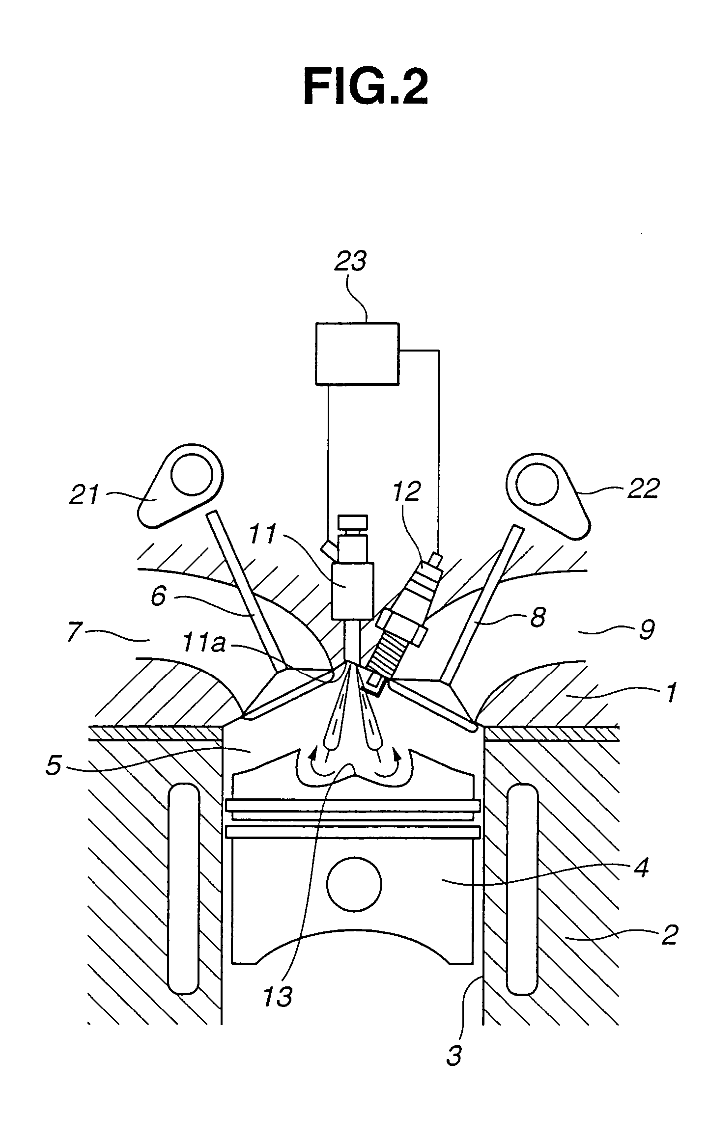
[0038]Referring to FIG. 2, there is shown a direct fuel injection type internal combustion engine of the present invention.

[0039]As shown, the engine generally comprises a cylinder head 1 with intake and exhaust ports 7 and 9, a cylinder block 2 with cylinders 3 (only one is shown) and pistons 4 (only one is shown). A combustion chamber 5 is defined in each cylinder 3 above the corresponding piston 4. Combustion chamber 5 is communicated with air intake port 7 through an intake valve 6, and communicated with exhaust port 9 through an exhaust valve 8. Intake valve 6 and exhaust valve 8 are driven to open and close by intake and exhaust valve actuating cams 21 and 22, respectively.

[0040]As shown, at an upper wall surface of combustion chamber 5, that is, at a portion of cylinder head 1 that defines an upper center part of the combustion chamber 5, there is arranged a f...


PUM


Abstract

A control unit is used for controlling a direct fuel injection type internal combustion engine. The control unit controls a fuel injection valve to have a first fuel injection mode wherein a penetration force of an injected fuel sharply increases at an initial stage of a fuel injection and thereafter an increasing rate of the penetration force gradually lowers with passage of time and a second fuel injection mode wherein the penetration force of the injected fuel sharply increases at a middle stage of the fuel injection. The control unit further controls the fuel injection valve in a manner to switch the first and second fuel injection modes in accordance with an operation condition of the engine.

Description

BACKGROUND OF THE INVENTION[0001]1. Field of the Invention[0002]The present invention relates in general to internal combustion engines and more particularly to the internal combustion engines of a direct fuel injection type in which fuel is directly injected into a cavity of the piston in each cylinder to produce an air / fuel mixture and the mixture is ignited by an ignition plug.[0003]2. Description of the Related Art[0004]One of the internal combustion engines of the above-mentioned direct fuel injection type is shown in Laid-open Japanese Patent Application (Tokkaihei) 11-82028, that enables a so-called stratified combustion.[0005]In the engine disclosed in the publication, each piston has a reentrant type cavity, and a fuel injection valve is arranged just above the cavity so that fuel is injected toward the cavity. That is, atomized fuel injected from the injection valve is forced to collide obliquely against a peripheral wall surface of the cavity to produce a circulation of t...

Claims


Application Information

Patent Timeline
Patent Type & Authority Patents(United States)
IPC IPC(8): F02B17/00F02B23/10F02B75/12F02M51/00F02D41/02F02D41/06F02D41/20F02D41/30F02D41/34F02D41/38F02D45/00F02M51/06F02M51/08F02M61/16F02M61/18F02M63/00
CPCF02M51/0603F02M61/162F02M61/1806F02B17/005F02B23/101F02D41/3836F02D2250/31Y02T10/125F02B2023/103F02B2075/125F02D41/3029Y02T10/123Y02T10/12
Inventor KUBO, MASAAKITERAJI, ATSUSHIHIRAYA, KOJIHOTTA, ISAMU
Owner NISSAN MOTOR CO LTD
Why Eureka
Try Eureka