Shift control system for hybrid vehicles

Active Publication Date: 2005-12-20
TOYOTA JIDOSHA KK
View PDF24 Cites 37 Cited by
  • Summary
  • Abstract
  • Description
  • Claims
  • Application Information

AI Technical Summary

Benefits of technology

[0007]A main object of the present invention is to suppress the growing of the electric power source for supplying the electric power to the elec

Problems solved by technology

When the torque capacity of the clutch is thus lowered at the shifting time of the transmission, however, there is a problem such that a driving torque or an acceleration is fluctuated due to lowering of the torque to be transmitted to the wheels.
However, there is a problem such that an electric power source such as a battery for supplying the electric

Method used


Image

  • Shift control system for hybrid vehicles
  • Shift control system for hybrid vehicles
  • Shift control system for hybrid vehicles

Examples


Embodiment Construction

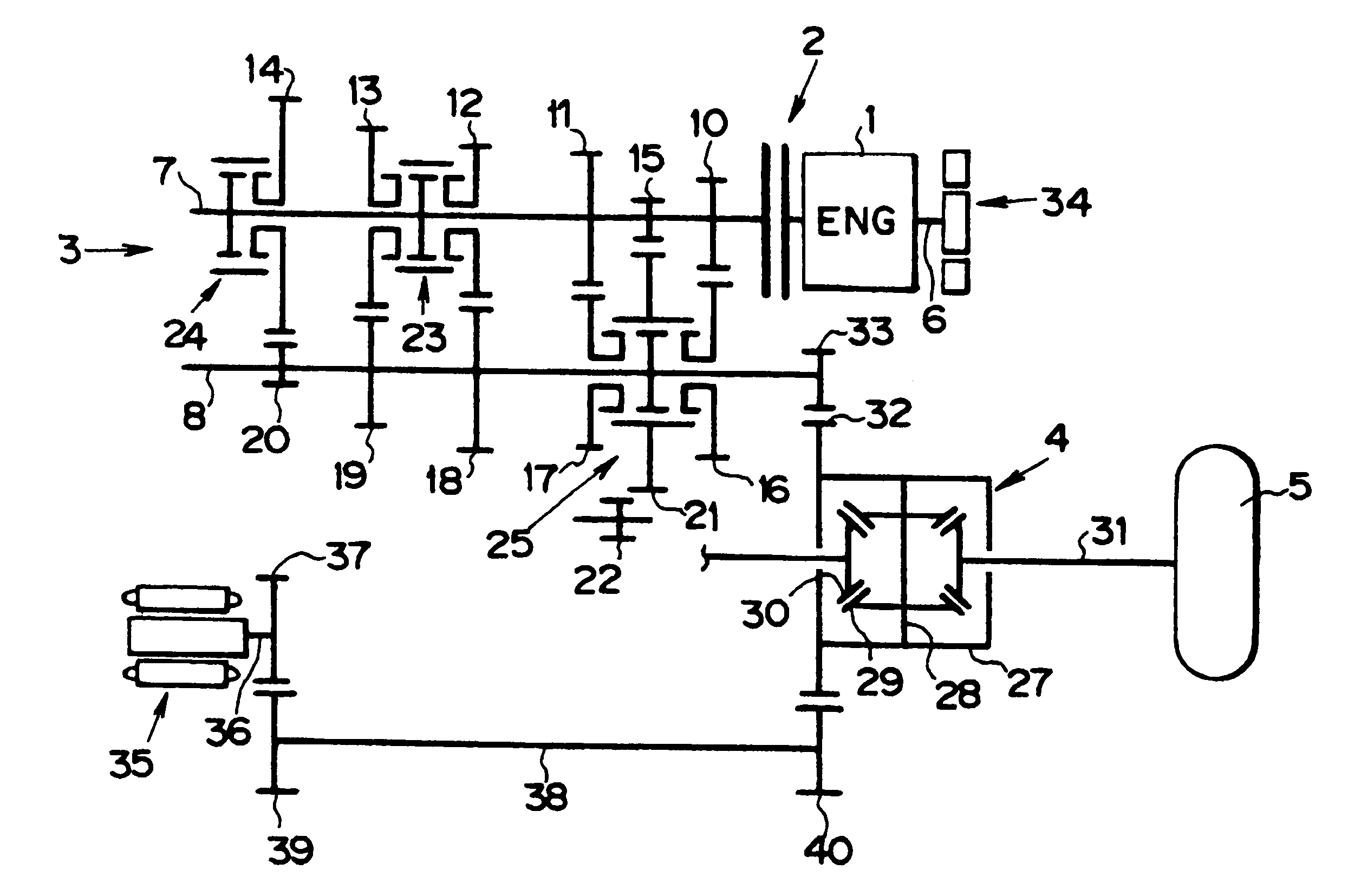
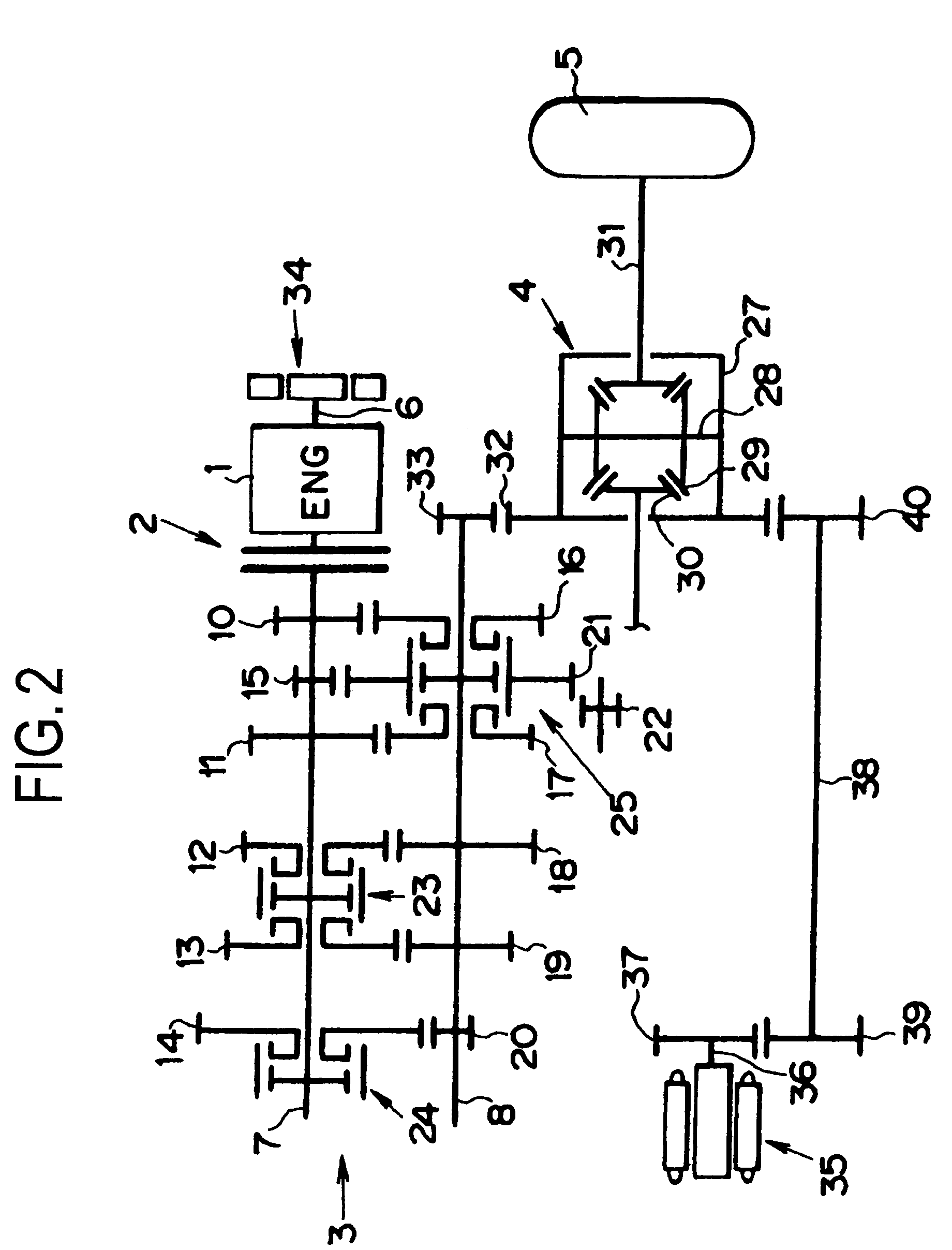
[0017]Next, this invention will be described with reference to a specific embodiment. One embodiment of a power train of a vehicle (a hybrid vehicle) Ve in which the present invention is applied is shown in FIG. 2, and a control system and an electric system of the vehicle Ve are shown in FIG. 3. According to the power train shown in FIG. 2, it is constructed to transmit a torque of a prime mover 1 to a wheel (front wheel) 5 through a clutch 2, a transmission 3, and a differential 4. The clutch 2 is constructed of a friction clutch, an electromagnetic clutch, a powder clutch and so on. The prime mover 1 is constructed of an internal combustion engine for example, and specifically, any of a gasoline engine, a diesel engine, a LPG engine or the like. Hereinafter, a case in which the gasoline engine is employed as the prime mover 1 will be described, and the prime mover 1 is called as an “engine 1” for the sake of convenience.

[0018]This engine 1 has a crankshaft 6, and the transmission...


PUM


Abstract

A shift control system for hybrid vehicles which is constructed to transmit a motive energy of the prime mover to a wheel via a clutch and a transmission, comprises an electric power generating means for generating an electric power by the motive energy of the prime mover, and for supplying the generated electric power to an electric motor, when executing a gear shift of the transmission and transmitting the motive energy of the motor to the wheel.

Description

BACKGROUND OF THE INVENTION[0001]1. Field of the Invention[0002]The present invention relates to a system for controlling a gear shift of a transmission in a hybrid vehicle which is provided with an electric motor in addition to an internal combustion engine or the like as a prime mover, and more specifically, to a shift control system intended for the hybrid vehicle which is constructed to transmit a motive energy of the motor to a wheel when a gear shift is executed.[0003]2. Related Art[0004]In the vehicle, which is provided with a clutch and a transmission between an engine and wheels, a control for lowering a torque capacity of a clutch at a shifting time of the transmission is known in the prior art. When the torque capacity of the clutch is thus lowered at the shifting time of the transmission, however, there is a problem such that a driving torque or an acceleration is fluctuated due to lowering of the torque to be transmitted to the wheels. In this connection, a technology w...

Claims


Application Information

Patent Timeline
IPC IPC(8): B60K1/02B60K6/24B60W20/00B60K6/26B60K6/36B60K6/387B60K6/40B60K6/442B60K6/547B60L50/16B60W10/00B60W10/04B60W10/06B60W10/08B60W10/10F16H3/089F16H61/04
CPCB60K6/48B60K6/547B60W10/08F16H3/089F16H61/0437B60W30/19B60K6/442B60K1/02Y10T477/26F16H61/682F16H63/502F16H2003/0818F16H2061/0433Y02T10/6221Y02T10/6234B60K2006/4808Y02T10/626Y10T477/27Y02T10/62
Inventor KOMEDA, OSAMUSASAKI, SHIZUOHASHIMOTO, YOSHIKIMURATA, HIROKIKITAMURA, YUICHIROSUZUKI, YOSHIHIDE
Owner TOYOTA JIDOSHA KK
Why Eureka
Try Eureka