
Crop re-hydration system utilizing a direct-fired steam generator having continuous water circulation

a technology of steam generator and steam cylinder, which is applied in the direction of steam generation using hot heat carriers, water feed control, lighting and heating apparatus, etc., can solve the problems of boiling water contained in water jackets, ruined bales, and same problems

Inactive Publication Date: 2005-12-27
DEERE & CO
View PDF4 Cites 4 Cited by
  • Summary
  • Abstract
  • Description
  • Claims
  • Application Information

AI Technical Summary

Benefits of technology

[0007]According to the present invention, there is provided an improved direct-fired steam generator system.
[0008]An object of the invention is to provide a direct-fired steam generator system including a water supply arrangement that avoids the problems associated with the prior art water supply arrangement. This object is accomplished by providing a water supply arrangement wherein the water first flows through the various cooling water jackets of the steam generator system and then is routed, by way of a three-way valve, normally to the water supply tank, and selectively to a water injection arrangement for injecting water into the bottom of the combustion cham

Problems solved by technology

A first drawback occurs during the procedure of starting up the steam generator for operation.
This causes wet spots in the hay, which may ultimately result in spoilage and, thus, in an entire bale being ruined.
A second drawback occurs during shut-down when water is pumped through the cooling jackets to cool the combustion chamber after the main flame has been extinguished.
This cooling water causes the same problems as that caused by the top-up water.
A third drawback occurs when the machine is shut down for the day, and water contained in the water jackets boils because the flow of fresh cooling water ceases when the water pump is shut off.
It has been observed that when water condenses on the pilot flame igniter or on the flame scanner, ignition difficulties arise and the scanner malfunctions.
Thus, the problem to be solved is to provide the necessary water for cooling the steam generator and for producing steam without causing the above-noted problems.

Method used


Image

  • Crop re-hydration system utilizing a direct-fired steam generator having continuous water circulation
  • Crop re-hydration system utilizing a direct-fired steam generator having continuous water circulation

Examples


Embodiment Construction

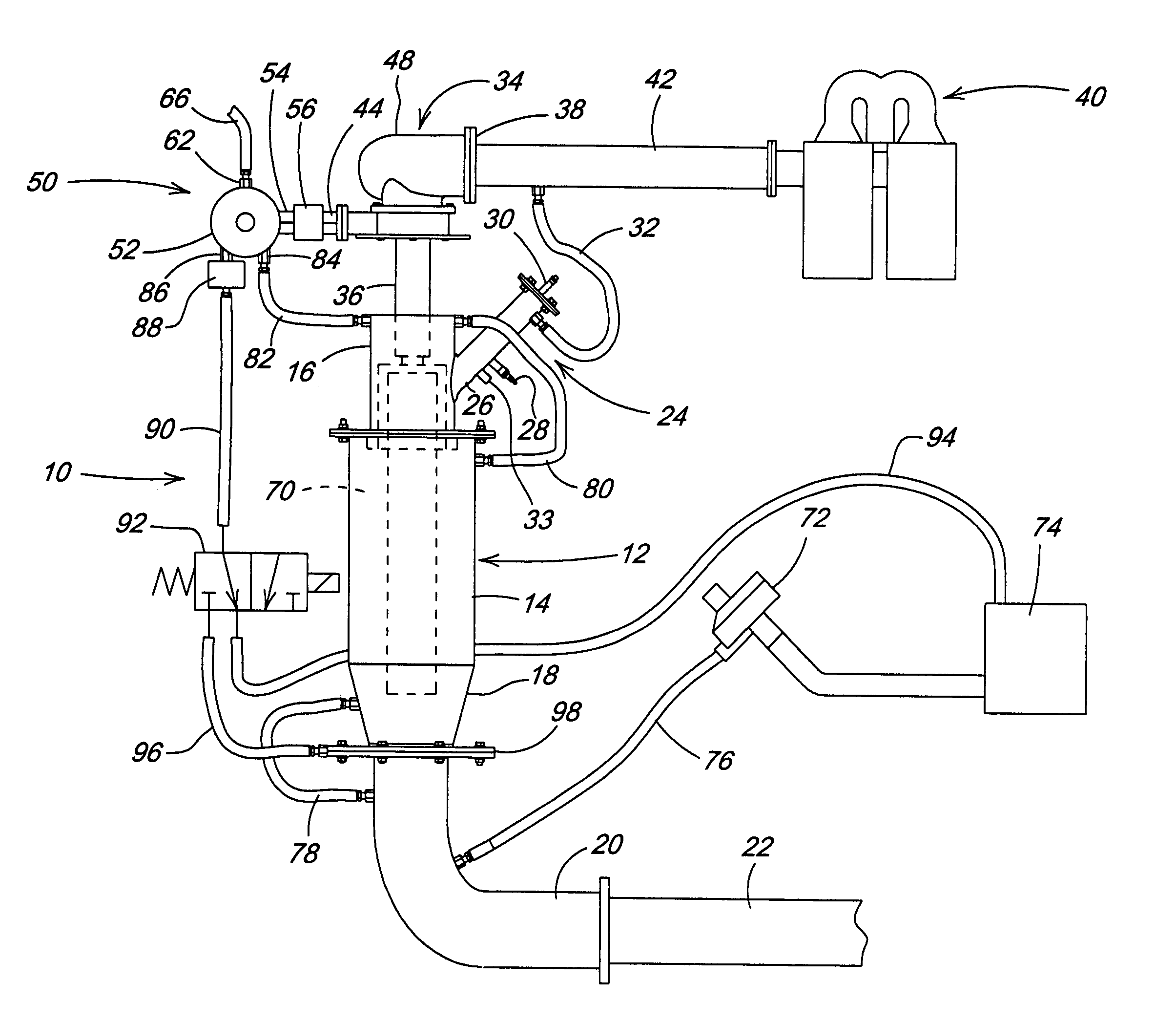
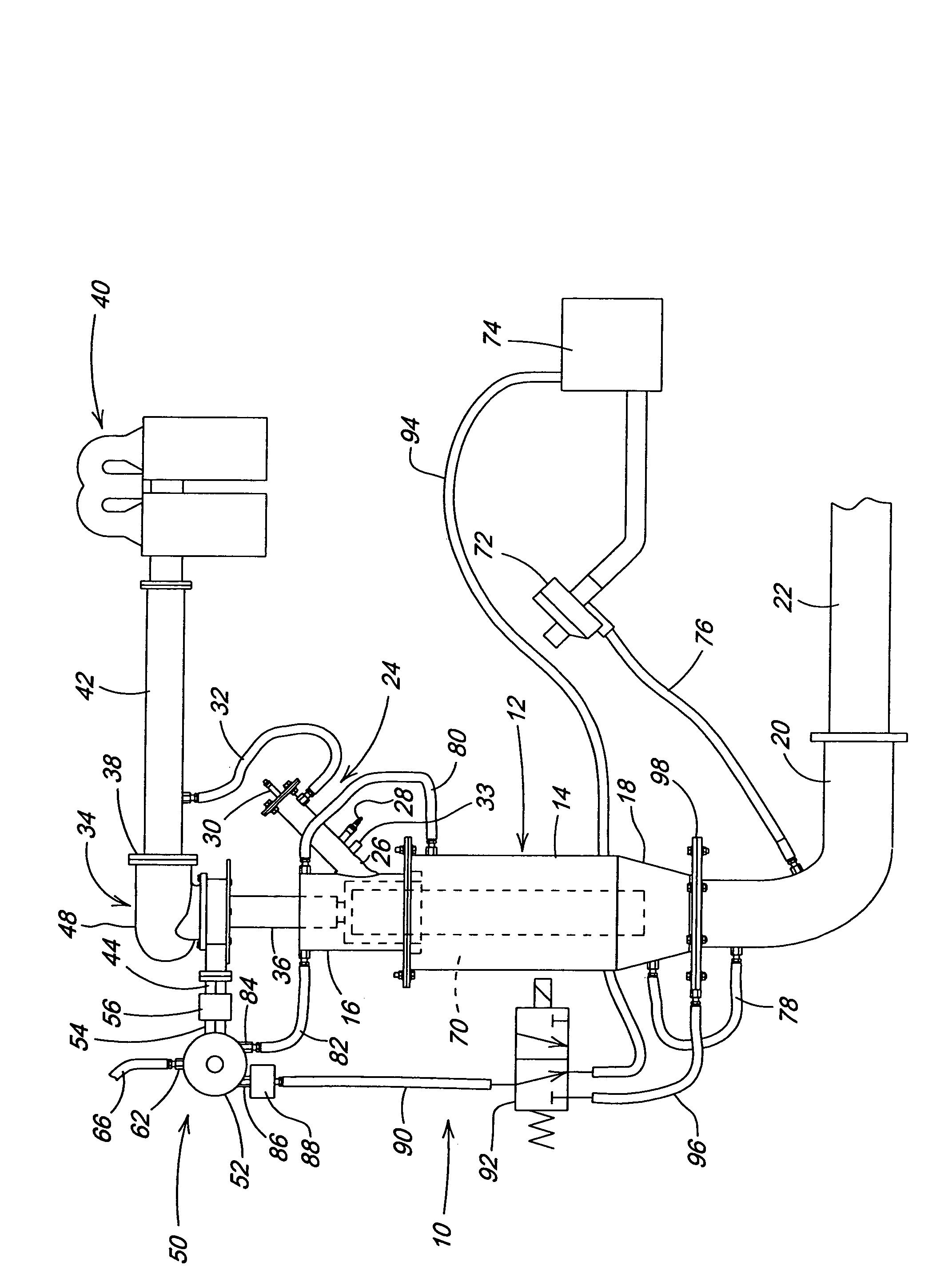
[0010]Referring now to the drawing, there is shown a direct-fired steam generator assembly 10 including a steam generator body 12 having a cylindrical inlet section 14 to which a cylindrical burner-head 16 is coupled, and having a conical outlet section 18 to which one end of an elbow 20 is coupled, the other end of the elbow 20 being coupled to a static mixer 22. A pilot burner arrangement 24 includes a tube 26 mounted so as to project though and terminate at an interior surface of a lower region of the burner-head 16. An igniter 28, which may be a spark plug or other type of sparking device, is mounted to the tube 26 so as to selectively create a spark at an interior location of the tube 26 for igniting a fuel / air mixture resulting when vaporized fuel enters by way of a pilot fuel inlet 30 provided in a cover at an inlet end of the tube 26 and when air enters by way of a pilot burner air line 32 coupled to an upper location of the tube 26. A flame sensor 33 is located below the ig...


PUM


Abstract

A direct-fired steam generator system is used in conjunction with a baler for providing steam for re-hydrating the crop being baled. Cooling water is pumped through water jackets defined by double walls surrounding the combustion chamber and adjacent components, with this water being routed exteriorly of the water jackets and back to a three-way water control valve provided for normally routing the water back to the cooling water reservoir. The control valve is selectively actuated to couple the returning water to an injector flange for metering the water into an outlet end of the combustion chamber only when a flame is present or soon to be present in the combustion chamber, whereby the water will come into contact with hot combustion gases and be changed to steam which is routed on to be applied to the crop being baled.

Description

FIELD OF THE INVENTION[0001]The present invention relates to crop re-hydration, and more particularly relates to a direct-fired steam generator particularly designed for use in crop re-hydration.BACKGROUND OF THE INVENTION[0002]The standard design for a direct-fired steam generator utilizes a once-through water system in which all feed water pumped into the water-jackets of the combustion chamber and adjacent components is injected into the exhaust stream of hot gases at the bottom the combustion chamber where it is changed into steam by the hot gases. This approach has several drawbacks.[0003]A first drawback occurs during the procedure of starting up the steam generator for operation. A water top-up is needed to ensure that the water jackets are completely filled before igniting the main flame. Since the water enters the water jackets under pressure, any excess is injected into the flame chamber. At this time, no hot gases are present to change the water to steam and this injected...

Claims


Application Information

Patent Timeline
IPC IPC(8): A01F15/08F22B1/26F22B1/28F22D1/28
CPCA01F15/0816F22B1/26F22B1/28
Inventor SCHLESSER, WALTER MARKLANG, ERIC RYANKRAUS, TIMOTHY JAMES
Owner DEERE & CO
Learn More